background image

Section 1: Introduction

LD610 User’s Technical Reference

Page 1-5

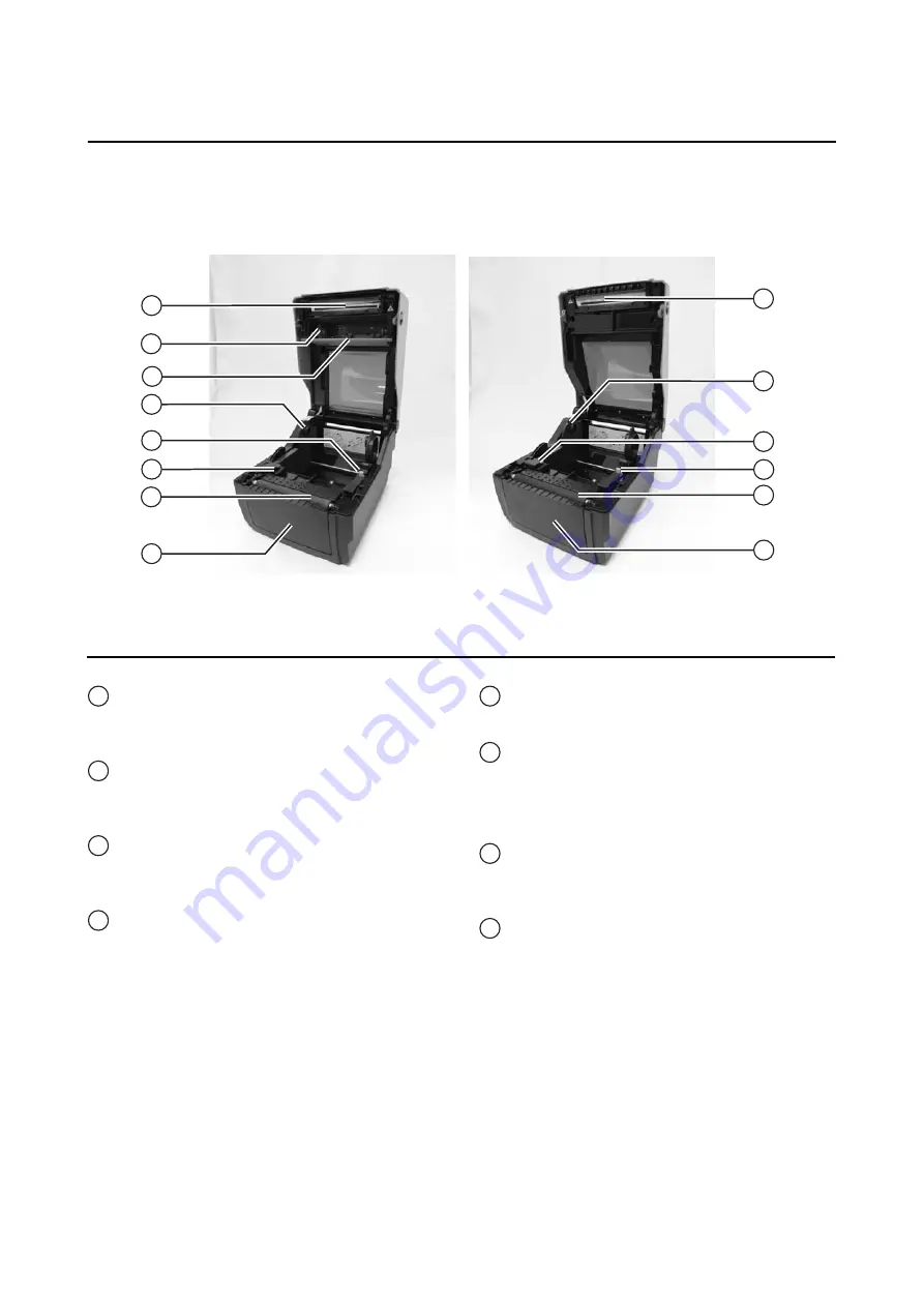
1.2 PARTS IDENTIFICATION (cont’d)

CG408DT/ CG412DT

CG408TT/ CG412TT

15

20

16

17
18

19

21

22

15

18

20
19
21

22

Internal view when Top cover is opened

Print head

This component is used to print on the media. 
Perform maintenance at regular intervals.

Ribbon unit

Used to load the ribbon and wind up the used 
ribbon.

Pull out lever

This is used to pull out the ribbon unit from the 
top cover for ribbon loading.

Roll media holder

To hold the roll media.

Media guide slide lever

Set to meet the size of the media used.

Media guide and I-Mark/ Gap sensor

A guide for the media to feed properly.

Detects the I-Mark on the media or gap of the 
label.

Platen roller

This roller feeds the media. Perform 
maintenance at regular intervals.

Optional device compartment

Used to install optional cutter or dispenser unit.

15

16

17

18

19

20

21

22

LD610 T

LD610 D

Summary of Contents for LD610 T

Page 1: ...User s Technical Reference 59103001 LD610 ...

Page 2: ... 2011 OKI Data Americas Inc ...

Page 3: ...e power cord Also do not place heavy objects on the power cord heat it or pull it because doing so could dam age the power cord and cause a fire or electric shock If the power cord becomes damaged core is exposed wires broken etc contact the dealer or Support Center Using the power cord in this condition could cause a fire or electric shock Do not modify excessively bend twist or pull the power co...

Page 4: ...hot devices Getting the power cord close to hot devices could cause the cord s covering to melt and cause a fire or electri cal shock When unplugging the power cord from the outlet be sure to hold it by the plug Pulling it by the cord could expose or break the core wires and cause a fire or electric shock The power cord set that comes with the printer is especially made for this printer Do not use...

Page 5: ...apid changes in temperature or humidity Exposure to these conditions may cause electrical problems within the printer Do not place the printer in a location subject to water or oil Do not place the printer in a location where it will be splashed with water or oil Water or oil entering inside the printer may cause a fire electric shock or malfunction Avoid dust Dust build up may result in poor prin...

Page 6: ... Mode 3 17 3 10 Error Occurrence While Downloading 3 17 3 11 Printer Configurations Setting 3 18 Troubleshooting 4 1 4 1 Error signal troubleshooting 4 2 4 2 Troubleshooting table 4 4 4 3 Interface troubleshooting 4 6 4 4 Test print troubleshooting 4 7 Cleaning and Maintenance 5 1 5 1 Cleaning The Print Head Platen and Rollers 5 2 5 2 How To Clean The Printer Cleaning Kit 5 2 5 3 How To Clean The ...

Page 7: ...pendix 8 1 8 1 Optional Accessories Cutter 8 2 8 2 Optional Accessories Dispenser 8 3 8 3 Positions of sensors and options 8 5 8 4 Operation Mode Selection 8 6 8 5 Base Reference Point 8 7 8 6 Offset position Adjustment 8 9 8 7 Paper End 8 10 8 8 Ribbon End 8 11 ...

Page 8: ...Table of Contents Page vi LD610 User s Technical Reference This page is intentionally left blank ...

Page 9: ... by the page number within the stated section This section assists you in unpacking the printer from the shipping container You will also be guided through a familiarization tour of the main parts and controls The following information is provided herein Features of the printer Unpacking Parts Identification 1 1 FEATURES OF THE PRINTER The LD610 Series is 4 inch Compact Desktop printer Thermal Tra...

Page 10: ...urred during shipping Please note that OKI shall hold no liability of any damage of any kind sustained during shipping of the product Notes If the printer has been stored in the cold allow it to reach room temperature before turning it on Please do not discard the original packaging box and cushioning material after installing the printer They may be needed in future if the printer needs to be shi...

Page 11: ... to turn the power on or off FEED LINE button Press this button to select the printer status online offline or to feed the media ERROR LED indicator The LED lights or blinks red when an error is detected in the printer During printer configuration setting the ERROR indicator responses in conjunction with the ON LINE POWER indicator to show the modes of the printer ON LINE POWER LED indicator The L...

Page 12: ...ut power terminal Supplies power to the printer by inserting the power cable via the AC adapter USB interface terminal To connect printer to the host computer using the USB interface RS 232C interface terminal To connect printer to the host computer using RS 232C interface Or to connect the optional Keypad Scanner or Smart keyboard to the printer LAN interface terminal To connect printer to the ho...

Page 13: ... wind up the used ribbon Pull out lever This is used to pull out the ribbon unit from the top cover for ribbon loading Roll media holder To hold the roll media Media guide slide lever Set to meet the size of the media used Media guide and I Mark Gap sensor A guide for the media to feed properly Detects the I Mark on the media or gap of the label Platen roller This roller feeds the media Perform ma...

Page 14: ...Section 1 Introduction Page 1 6 LD610 User s Technical Reference This page is intentionally left blank ...

Page 15: ...sists you in installing consumable media in the printer as well as adjustment instructions and installing other optional attachment units The following information is provided 2 1 Site Location 2 2 Media Selection 2 3 Loading Labels 2 4 Loading the Carbon Ribbon For LD610 T only 2 5 Connections ...

Page 16: ...r to tread on it and wear it out The media edge will also wear a groove in the platen roller which can affect print quality This printer can print on roll media or fan folded media The methods used for loading roll media and fan folded media differ The printer uses sensors to detect I Marks or gap on the media in order to precisely position the print content Note For optimal print performance and ...

Page 17: ...ests firmly so that it will not fall forward and injure your hands 2 While holding the media guide slide lever adjust the width of the media holder to match the media size 3 Load the media onto the media holder 4 After pulling out the media pass the media through the media guides and place the leading edge of the media on top of the platen roller Note Make sure the printed side of the media is fac...

Page 18: ...er and Section 8 2 Optional Accessories Dispenser on how to route the media 6 After loading the media turn on the power The printer is online and the ON LINE POWER indicator lights green When the printer is ready press the FEED LINE button to output the leading part of the media Caution When replacing media bear in mind that the print head and its surrounding area remain hot Keep your fingers away...

Page 19: ... Note Make sure the printed side of the media is facing upwards 3 While holding the media guide slide lever adjust the width of the media holder to match the media size After pulling out the media pass the media through the media guides and place the leading edge of the media on top of the platen roller 4 Close the top cover until it clicks into position Notes Be careful not to get your fingers pi...

Page 20: ...EED LINE button to output the leading part of the media 2 3 3 Overview of the Roll media and Fan folded media loading path Caution When replacing media bear in mind that the print head and its surrounding area remain hot Keep your fingers away from these areas to prevent injury Avoid touching even the edge of the print head with your bare hands ON LINE POWER Roll media Face in Roll media Face out ...

Page 21: ...ce that is made visible through the application of heat from the print head In this case there is no need of loading the carbon ribbon 1 With the power supply off pull the cover open close latches on both sides of the printer toward you to unlock the top cover and then open the top cover Note Make sure that the cover rests firmly so that it will not fall forward and injure your hands 2 Pull the le...

Page 22: ...bon roll to the left of the ribbon supply unit Turn the ribbon roll until the core snaps on the protrusion of the left ribbon supply unit Note Use only genuine OKI carbon ribbons for maximum print quality and printer durability 4 Mount the empty ribbon core on the ribbon wind up unit the same manner as in step 3 above When loading the carbon ribbon for the first time use the empty ribbon core supp...

Page 23: ... The dull side ink side of the ribbon should be facing outward as it travels through the print head assembly 6 Close the top cover until it clicks into position Note Be careful not to get your fingers pinched while closing the top cover 7 After loading the media and the carbon ribbon do a test print to check that the media roll and ribbon have been loaded properly See Section 3 3 User Test Print M...

Page 24: ...ace on board 3 USB and IEEE 1284 interface on board Connect only one type of interface cable from the printer to the host computer Use the cable that is compatible with the standard of the interface board as stated in Section 7 Interface Specifications Make sure the cable is correctly oriented Caution Never connect or disconnect interface cables or use a switch box with power applied to either the...

Page 25: ...ected with LD610 Series printer 1 Make sure that power cable is not connected to the printer 2 Connect the cable from the optional device to the RS232C terminal at the back of the printer Note Make sure the connector is correctly oriented Secure the printer with one hand and insert the connector firmly 3 Set the printer for use with the connected device Refer to Section 3 5 Operation Setting Mode ...

Page 26: ...0 60 Hz A 3 pin plug is attached to the power cord provided with your printer One of these pins is the ground wire You must use a 3 pin power outlet The plug will not work with a 2 pin power outlet The shape of the power plug may vary depending on the location where the printer was purchased Warning Be sure to connect the ground wire Failure to do so may cause an electric shock Do not operate the ...

Page 27: ... 5 6 Turning Off the Power When you have completed the printing job turn the printer off Be sure to confirm that the printer is in the offline status Press and hold the POWER button until the ERROR indicator displays red and then turns off If there is any printed paper remaining in the printer cut it off Warning Do not operate the power switch or insert remove the power cable while your hands are ...

Page 28: ...Section 2 Installation Page 2 14 LD610 User s Technical Reference This page is intentionally left blank ...

Page 29: ... are based Most of the printer s settings are controlled via standard SBPL commands or by using the provided OKI Utilities Tool application Some printer settings may be manually configured via the POWER and FEED LINE buttons with the ON LINE POWER indicator and ERROR indicator on the front of printer All of the printer s buttons are used either singularly or together to perform configuration activ...

Page 30: ...nter is in normal mode this two indicators notifies the user of various status conditions During different operation modes the ON LINE POWER and ERROR indicators turn on and flash differently In this section the combination of the following symbols has been used to describe the indicator lighting sequence Refer to the example listed below for lighting sequences The repeating patterns are as shown ...

Page 31: ...dicators lighting sequence The following flow chart provides a clear summary of each of the modes and its access method Printer Start up Normal Mode Online Press POWER button Power off Operation setting Mode While pressing FEED LINE button press POWER button User Test Print Mode Holding FEED LINE button Factory Test Print Mode Holding FEED LINE button Operating Mode ON LINE POWER ERROR Procedures ...

Page 32: ... User Test Print mode First ensure that you have pressed the FEED LINE button to pause the test printing then press POWER to turn off the printer Printer start up While pressing FEED LINE button press and release POWER button Keep holding FEED LINE button Green light Release FEED LINE button when ON LINE POWER indicator changes to green light and single short beep sound is heard Blinking green lig...

Page 33: ... DOT 4 Cut Offset Cut position offset value 099 DOT 5 Peel Offset Peel off position offset value 099 DOT 6 Tear Off Offset Tear off position offset value 099 DOT 7 Label Size Label size Pitch Width P x W DOT 8 Print Speed Print speed 50mm s 75mm s 100mm s 9 Print Darkness Print darkness 1A 5A 10 Operation mode Operation mode CUT NONE SEPA TEAR OFF DISPENSER CONTINUOUS 11 Sensor Type Sensor type Ga...

Page 34: ...ASH Zero slash 10 EURO Euro code No Print Item Contents of the print data 1 Selected Interface In use interface USB RS 232C Keypad Scanner 2 Interface 1 Interface 1 USB 3 Buffer Type Buffer type Multi 4 Protocol Protocol Driver 5 Serial No Serial No Serial No None 6 Interface 2 Interface 2 RS 232C Communication parameters 19200 8 N 1 Baud rate bps 9600 19200 384000 Data length bit 8 7 Parity N O E...

Page 35: ...ype Buffer type Multi 1 item 8 Protocol Protocol Driver No Print Item Contents of the print data 1 Selected Interface In use interface USB LAN 2 Interface 1 Interface 1 USB 3 Buffer Type Buffer type Multi 4 Protocol Protocol Driver 5 Serial No Serial No Serial No None 6 Interface 2 Interface 2 LAN 7 Buffer Type Buffer type Multi 8 Protocol Protocol Driver CYC Driver ENQ Status3 9 MAC Address MAC a...

Page 36: ... First ensure that you have pressed the FEED LINE button to pause the test printing then press POWER to turn off the printer Printer start up While pressing FEED LINE button press and release POWER button Keep holding FEED LINE button Green light Release FEED LINE button when ERROR indicator changes to red light and two short beeps sound are heard Blinking green light Press FEED LINE button to sta...

Page 37: ... is printed for direct thermal print 2 Firm Ver Printer F W version 3 Firm Date Printer F W creation date YY MM DD 4 Font Version Font version 5 Serial No Serial No Serial No None 6 Life Counter Life counter Km 7 Head Counter1 Head counter 1 Km 8 Head Counter2 Head counter 2 Km 9 Head Counter3 Head counter 3 Km 10 Cutter Counter Cutter counter 11 Thermistor Print head temperature 0 to 255 12 Senso...

Page 38: ...ffset Peel off position correction value 099 DOT 6 Tear Off Offset Tear off position correction value 099 DOT 7 Label Size Label size Pitch Width P x W DOT 8 Print Speed Print speed 50mm s 75mm s 100mm s 9 Print Darkness Print darkness 1A 5A 10 Sensor Type Sensor type Gap I Mark None 11 Sensor Level Low Average minimum value of pitch sensor V 12 Sensor Level High Average maximum value of pitch sen...

Page 39: ...own below Printer start up While pressing FEED LINE button press and release POWER button Keep holding FEED LINE button Green light Release FEED LINE button when ON LINE POWER indicator changes to blinking green light and three short beeps sound are heard 1 2 Printer status Procedures The printer will cyclically advance to next mode as long as the FEED LINE button is held down Off ON LINE POWER in...

Page 40: ...king green light Off Three short beeps Off Red light Off Blinking red light Off Blinking red light Blinking green light Blinking red light Blinking green light longest blink interval Blinking red light longest blink interval Blinking red light longest blink interval Blinking green light longest blink interval Off Press the FEED LINE button repeatedly to select different operation setting mode cycl...

Page 41: ... computer to download into its memory Remember to set the printer to the correct active interface to be used for the data transfer Status of printer in Program Download Mode ON LINE POWER indicator ERROR indicator Buzzer Activation via operation setting mode or download command Start up Reception from interface Yes Reboot command reception Program data reception Yes Yes No No No Download Download ...

Page 42: ...ERROR indicators respond differently from above mentioned procedure an error may have occurred Please refer to Section 3 10 Error Occurrence While Downloading for details 3 6 1 Firmware Download The following listed the downloadable firmware according to the connected interface Downloadable x Undownloadable Not available Caution Downloading firmware will initialize all the previous settings set by...

Page 43: ...Occurrence While Downloading for details Status of printer in Font Download Mode ON LINE POWER indicator ERROR indicator Buzzer Activation via operation setting mode or download command Start up Reception from interface Yes Reboot command reception Font data reception Yes Yes No No No Download Download completion Reboot and start in normal mode Online At the start of download mode Wait to receive ...

Page 44: ...Horizontal 0 dot 2 Pitch Offset 0 dot 3 Cut Offset 0 dot 4 Dispensing Offset 0 dot 5 Tear Off Offset 0 dot 6 Label Size Pitch 896 dot x Width 832 dot 203 dpi 7 Print Speed 75 mm sec 3 Inches sec 8 Print Darkness 3A 9 Sensor Type Gap 10 Paper End Search Roll 11 Zero Slash Enabled 12 Proportional Pitch Enabled 13 Initial Feed Disabled 14 Auto Feed Disabled 15 Operation mode Continuous No setting Tea...

Page 45: ...ont download 1 The flash ROM may be in a state that fails to permit data being written to it 2 Incorrect data are received while transferring downloaded data 3 10 1 Operation Status when having an Error in Downloading Process The ERROR indicator and buzzer response when having an error in downloading process are as follows Operation status ON LINE POWER indicator ERROR indicator Buzzer Flash ROM e...

Page 46: ...nt darkness level 1 to 5 9 Sensor type I Mark Gap Sensor off Transmissive CX com patible 10 Zero slash Disabled Enabled 11 Kanji code JIS code SJIS code 12 Initial feed Disabled Enabled 13 Character pitch Fixed Proportional 13 Option Waiting time 5 to 200 x100ms 14 Media size Pitch 1 to 2400 dots including liner backing paper LD610 T D 15 Width 1 to 832 dots including liner backing paper LD610 T D...

Page 47: ... 3 Protocol for driver STATUS4 ENQ response 3 1 port connection ENQ response STATUS3 28 IEEE 1284 inter face 4 Buffer type Multi 1 item ACK width 010 to 200 1 50ns 28 Non standard code Nonstandard code switching Standard code Nonstandard code 29 Nonstandard code setting Nonstandard code settings for STX ETX ESC ENQ CAN NULL OFFLINE 30 Download Firmware download Download firmware from the host comp...

Page 48: ...Section 3 Operation and Configuration Page 3 20 LD610 User s Technical Reference This page is intentionally left blank ...

Page 49: ...e printouts on the LD610 Series printer use this section to make sure the basics have been checked before deciding you are unable to proceed any further This section is divided into four parts 4 1 Error signal troubleshooting 4 2 Troubleshooting table 4 3 Interface troubleshooting 4 4 Test print troubleshooting ...

Page 50: ...ng information FROM error 1 FLASH ROM read write error 2 Exceeded the FLASH ROM write count limits 1 2 Board replacement Machine error 1 Board defect 1 Board replacement Program error Incorrect program error Off Solid red 1 Download did not complete successfully 1 Download again Communication error Communica tion error by kit Off Red Off x twice Red x twice Off blinks with changing inter val 1 lon...

Page 51: ... of paper 1 Set the paper properly Ribbon end 1 Out of ribbon or ripped ribbon 2 Ribbon is not set properly 1 2 Set the ribbon properly Option Cutter error Off long blink interval 3 short beeps sound 1 Cutter is not connected 2 Cut operation was not performed successfully 1 Connect the cutter unit 2 Set and feed the paper again Warning Buffer near full Blinking green Lights alternately Blinking re...

Page 52: ...a input error Ensure correct data stream Defective main circuit board Have OKI authorized servicing personnel replace main board PRINTER CREATES A BLANK LABEL Data input error Ensure correct data stream Incorrect label sensor selection Set the sensor correctly by printer setting tool Print head is disconnected Power off the printer and ensure a proper connection Defective print head Replace print ...

Page 53: ...rint head Defective print head Replace print head as required SMEARED PRINT IMAGES Poor media quality Use higher quality media Use only OKI certified media Foreign material on print head and platen roller Clean print head and platen roller Foreign material on labels Use higher quality media Use only OKI certified media Excessive print head energy Adjust darkness level setting Excessive print speed...

Page 54: ...that procedure within this manual for instructions The command stream should be continuous and possess 0Dhex and or 0Ahex carriage return and line feed characters throughout However there should not be either located between the start ESC A and the stop ESC Z commands Try another port to isolate the problem Replace the main circuit board if determined to be the problem LAN ETHERNET INTERFACE CHK T...

Page 55: ... host s peripheral settings are set to ECP for faster throughput Refer to the computer manufacturer s documentation for details Ensure the printer is receiving information from the computer using the Receive Buffer Hex Dump mode Refer to that procedure within this manual for instructions The command stream should be continuous and possess 0Dhex and or 0Ahex carriage return and line feed characters...

Page 56: ...Section 4 Troubleshooting Page 4 8 LD610 User s Technical Reference This page is intentionally left blank ...

Page 57: ... Print Quality Caution When cleaning the print head bear in mind that the print head and its surroundings may be hot Wait until the printer cools down before proceeding to clean the printer Be sure to turn off the power before cleaning The suggested cleaning schedules here are just guidelines If necessary clean as appropriate depending on the degree of contamination Use a cleaning pen cotton swab ...

Page 58: ...HE PRINTER CLEANING KIT If you are using a carbon ribbon be sure to remove it before cleaning Follow the instructions supplied with the cleaning kit Use the items to clean the following parts 1 Before starting get ready an approved cleaning kit from your OKI representative Make sure the printer is powered off and remove the power cable 2 Lift the Top Cover 3 Remove the media and the ribbon Cleanin...

Page 59: ... debris on the print head 1 Make sure the printer is powered off and remove the power cable 2 Lift the Top Cover 3 Remove the media and the ribbon 4 Place the head cleaning sheet between the print head and the platen roller The coarse side of the cleaning sheet should face the surface of the print head elements 5 Close the top cover with approximately 25mm 1 inch of the cleaning sheet extended out...

Page 60: ...ad assembly to the right and pull the whole print head assembly downward 4 The cable connectors circled at the rear of the print head is now exposed Pull the print head downward then gently disconnect the defective print head from the cable connectors 5 Carefully connect the cable connectors to a replacement print head The white cable should be connected to the left connector while black cable sho...

Page 61: ...ttached to the top cover frame At the same time fix the fulcrum shaft of the print head bracket to the hooks While pressing the print head slide the side tab upwards to lock the print head assembly in place 8 Close the Top Cover 9 Restore power reload media reset the head counter and perform a test print to ensure that the print head is connected properly Fulcrum shaft Circular recess Hooks ...

Page 62: ...2 Lift the Top Cover 3 Locate the two platen bearings on each side of the platen roller and turn the handles in the direction as shown 4 Lift up the defective platen roller assembly with the handles and replace it with a new one 5 Follow the above steps in reverse sequence to reassemble the parts Make sure that the platen bearing snaps back in position Perform a label feed to ensure the platen rol...

Page 63: ...sed to activate the print head heating elements It is important to find a proper print darkness level based on your particular label The printed images should not be too light nor should the edges of text or graphics be smudged Instead the edges of each image should be crisp and well defined The adjustment can be made via standard SBPL commands or by the Utilities Tool application Print Speed The ...

Page 64: ...Section 5 Cleaning and Maintenance Page 5 8 LD610 User s Technical Reference This page is intentionally left blank ...

Page 65: ...mes 50 Watts During standby 2 5 Watts ENVIRONMENTAL EXCLUDING MEDIA Operating Temperature 4 to 38 C 39 2 to 100 4 F Storage Temperature 10 to 60 C 14 to 140 F Operating Humidity 30 to 80 RH Non condensing Storage Humidity 15 to 85 RH Non condensing PRINT Method DT models Direct Thermal only TT models Thermal Transfer and Direct Thermal Print Speed selectable 50 75 or 100 mm second 2 3 or 4 Inches ...

Page 66: ... 25 to 303 mm 0 98 to 11 93 Width 22 to 107 mm 0 87 to 4 21 Width including liner 25 to 110 mm 0 98 to 4 33 Pitch 22 to 100 mm 0 87 to 3 93 Pitch including liner 25 to 103 mm 0 98 to 4 05 Width 22 to 107 mm 0 87 to 4 21 Width including liner 25 to 110 mm 0 98 to 4 33 Pitch 22 to 300 mm 0 87 to 11 8 1 Pitch including liner 25 to 303 mm 0 98 to 11 93 Width 22 to 107 mm 0 87 to 4 21 Width including l...

Page 67: ...Select one of the following The factory will provide the unit with the selected interface 1 USB 2 0 Type B with RS 232C D SUB 9 pin type or 2 USB 2 0 Type B with LAN 10BASE T 100BASE TX Automatic Switching or 3 USB 2 0 Type B with IEEE1284 The RS 232C connector can be used to connect the printer to a computer an optional keypad Smart keyboard or Barcode scanner SENSING Gap Transmissive Sensitivity...

Page 68: ...umeric characters and symbols XS 17 dots W x 17 dots H Alphanumeric characters and symbols XM 24 dots W x 24 dots H Alphanumeric characters and symbols XB 48 dots W x 48 dots H Alphanumeric characters and symbols XL 48 dots W x 48 dots H Alphanumeric characters and symbols OA Font OCR A 15 dots x 22 dots Alphanumeric characters and symbols 15 dots x 22 dots Alphanumeric characters and symbols OB F...

Page 69: ...C B CC C GS1 DataBar Composite CC A CC B GS1 DataBar Truncated Composite CC A CC B GS1 DataBar Stacked Composite CC A CC B GS1 DataBar Stacked Omni Directional Composite CC A CC B GS1 DataBar Limited Composite CC A CC B GS1 DataBar Expanded Composite CC A CC B GS1 DataBar Expanded Stacked Composite CC A CC B GS1 DataBar is new version of RSS 14 Ratios 1 2 1 3 2 5 User definable bar widths Magnific...

Page 70: ...it 2 Dispenser Unit 3 RTC kit Calendar IC 4 Linerless Nonesepa Unit 5 Keypad 6 Compatible smart keyboard 7 Compatible 1D barcode scanner Applicable to USB and RS232C interface model only Connect to RS232C terminal REGULATORY COMPLIANCE Safety regulation UL60950 1 2001 USA CSA22 2 No 60950 1 30 Canada EN60950 1 CE Europe CCC GB4943 2001 China EMC regulation FCC15B Class B USA Canada CE EN55022 EN55...

Page 71: ... and environment Refer to OKI representative on the labels to be used Perforated liner and split liner cannot be used Peel end labels Media Size Pitch 22 to 100 mm 0 86 to 3 93 Pitch including liner 25 to 103 mm 0 98 to 4 05 Width 22 to 107 mm 0 86 to 4 21 Width including liner 25 to 110 mm 0 98 to 4 33 Thickness 0 06 to 0 19 mm 0 0024 to 0 0074 Sensor Type Dispenser sensor Reflective type LINERLE...

Page 72: ...Section 6 General Specifications Page 6 8 LD610 User s Technical Reference This page is intentionally left blank ...

Page 73: ...s USB Interface 7 5 Local Area Network LAN Ethernet 7 1 INTERFACE TYPES The LD610 Series has three types of Main PCBs Each type of PCB is equipped with two different interface types for performing data communication with the host These are described as follows 1 Type 1 USB and LAN on board 2 Type 2 USB and RS232C on board 2 Type 3 USB and IEEE1284 on board Caution Never connect or disconnect inter...

Page 74: ...e Cable length 5m or less Communication settings Use Printer configuration tool or I2 command to setup I2 abcde Parameter Item Value Description a Baud rate 2 38400bps 1 19200bps Default 0 9600bps b Data bit length 1 7 bits 0 8 bits Default c Parity bits 2 EVEN 1 ODD 0 NONE Default d Stop bits 1 2 bits 0 1 bit Default e Protocol 4 STATUS 3 3 Protocol for driver STATUS 4 Default 2 XON XOFF 1 READY ...

Page 75: ...top bits to end each byte transmission Protocol setting Selects the flow control and status reporting protocols Synchro system Asynchronous method Maximum receive buffer capacity 1MB Code ASCII 7 bits Graphic 8 bits Transmission form Note If using 7 bits b8 will be omitted Signal level High level Low level 5 to 12V 5 to 12V Interface type Use Printer configuration tool or DI command DI a Parameter...

Page 76: ... print labels may cause the printer not to print the first print data approximately 120 bytes To avoid this problem it is necessary to attach approximate 120 bytes of dummy data by application software that enables the host to send the data for printing labels For example When sending STX A V 20 H 20 P 2 L 0202 X20 1234 Q 2 Z ETX transfer the appropriate 120 bytes of dummy data shown below 00H 00H...

Page 77: ... Return Status STATUS 3 and Protocol for Driver STATUS 4 The purpose of these protocols is to control printer status on the host side With the request command from the host the status is returned from the printer After receiving the request command the status is returned immediately In these communication protocols receive mode is set to multi item buffer When the print data STX ESC A ESC Z ETX is...

Page 78: ...ivalent Cable length 1 5m or less Signal level High level Low level 2 4 to 5 0V 0 0 to 0 4V Communication condition setting Use the I1 command for the following settings Item Color Receive mode Single item buffer Multi item buffer ACK width 010 to 200 1 50ns Communication protocol cannot be fixed at compatible mode because of IEEE1284 negotiation Interface type Use Printer configuration tool or DI...

Page 79: ...No Signal I O 1 STROBE Input 19 STROBE RETURN 2 DATA 1 Input 20 DATA 1 RETURN 3 DATA 2 Input 21 DATA 2 RETURN 4 DATA 3 Input 22 DATA 3 RETURN 5 DATA 4 Input 23 DATA 4 RETURN 6 DATA 5 Input 24 DATA 5 RETURN 7 DATA 6 Input 25 DATA 6 RETURN 8 DATA 7 Input 26 DATA 7 RETURN 9 DATA 8 Input 27 DATA 8 RETURN 10 ACK Output 28 ACK RETURN 11 BUSY Output 29 BUSY RETURN 12 PE Output 30 PE RETURN 13 SELECT Outp...

Page 80: ... bit ACK Output Low active pulse signal indicating the completion of receive data import BUSY Output High active signal indicating that the printer is not ready to receive data PE Output High active signal indicating paper shortage SELECT Output High active signal indicating that the printer is ready to receive data AUTOFD Input Signal for the IEEE1284 standard CHASSIS GND Connecting to framework ...

Page 81: ...all three types of boards 7 4 2 Pin Assignments Interface connector Series B plug Cable length 5m or less Twisted Pair Shielded Version USB 2 0 Maximum receive buffer capacity 1MB Interface type Use Printer configuration tool or DI command DI a Parameter Item Value Description a Interface 0 USB 1 RS 232C LAN IEEE1284 2 Keypad 3 Scanner Smart keyboard Pin No Description 1 VBus 2 Data D 3 Data D 4 G...

Page 82: ...e USB port As for the USB driver installation procedure refer to How to Install the USB Standard Print Support in the printer driver installation specifications Notes OS environment corresponding to the USB interface is Windows2000 XP Server2003 Vista however the connection may not be established depending on the manufacturers or models For more details refer to your host computer documentation US...

Page 83: ...ipment The LINK is established by Auto Negotiation LED Color Conditions LINK Green Lights up when establishing the LINK SPEED Orange Lights off when recognizing the destination 10BASE T Lights up when recognizing the destination 100BASE TX COLLISION Red Lights up when collision occurs Maintenance function Printing LAN configuration information LAN configuration information will be printed on the t...

Page 84: ...ollowing settings can be configured via the Printer configuration tool or com mands Item Command Setting range LAN mode I3 Protocol for driver STATUS4 cyclic response mode 1 Protocol for driver STATUS4 ENQ response mode 1 STATUS3 2 IP address W1 0 0 0 0 255 255 255 255 Subnet mask W2 0 0 0 0 255 255 255 255 Gateway address W3 0 0 0 0 255 255 255 255 IP address setup WI Manual DHCP RARP WM RARP dis...

Page 85: ...logical printer name as queue name such as lp sjis and euc When sending a job by LPR the transmission order of data file control file within the job does not affect the printing operation Notes A job deletion by LPR is not supported LPD is available only for Protocol for Driver STATUS4 If executing a large quantity of printing by LPD some parts of the data may be missing due to the Windows specifi...

Page 86: ...s variables TCP IP related settings Variable identifier Default Factory setting Setting range IP address 0 0 0 0 Externally obtained 0 0 0 0 255 255 255 255 Subnet mask 0 0 0 0 Derived from IP address 0 0 0 0 255 255 255 255 Gateway address 0 0 0 0 Invalid 0 0 0 0 255 255 255 255 RARP protocol ENABLE ENABLE DISABLE DHCP protocol ENABLE ENABLE DISABLE Keep alive time 180 sec 30 300 Socket cancel No...

Page 87: ...and open the port at intervals of approximately 150ms to 200ms If you don t have enough time from closing to opening the port it may result in double connection If the host requests the connection to the port already connected Port1024 Port1025 or Port9100 the printer accepts the request establishing double connection however the printer disconnects the second connection immediately 3 Do not conne...

Page 88: ...Section 7 Interface Specifications Page 7 16 LD610 User s Technical Reference This page is intentionally left blank ...

Page 89: ...PPENDIX The following information is provided 8 1 Optional Accessories Cutter 8 2 Optional Accessories Dispenser 8 3 Positions of sensors and options 8 4 Operation Mode Selection 8 5 Base Reference Point 8 6 Offset position Adjustment 8 7 Paper End 8 8 Ribbon End ...

Page 90: ...er Cutting of Labels The correct cutting position is at the label gap Cutting onto the label must be avoided because the label adhesive that accumulates on the blade will affect cutter sharpness Cutting Media with Perforation As for media with perforation cutting on or in front of the perforated lines is prohibited Cutting in those locations could cause the media to jam and the printer to malfunct...

Page 91: ...oth sides of the printer toward you to unlock the top cover and then open the top cover Make sure that the cover rests firmly so that it will not fall forward and injure your hands 2 With your thumbs positioned on the two corners of the pressure bracket push the pressure bracket up and pull it forward to open the pressure bracket 3 Peel off the first two leading labels from the liner back ing pape...

Page 92: ...he label is loaded correctly 8 2 2 Stop position Adjustment Normally the label is dispensed to the point where 2 or 3mm 0 08 or 0 1 of the label remain on the liner backing paper If the label is not dispensed at the regular position you can change the offset setting with the SBPL commands After adjusting the stop position dispense two or three labels to fix the stop position Notes There may be cas...

Page 93: ... s Technical Reference Page 8 5 8 3 POSITIONS OF SENSORS AND OPTIONS 7 3mm 0 29 5 0mm 0 19 46 3mm 1 82 I Mark sensor Gap sensor 34 9mm 1 37 20 6mm 0 81 21 1mm 0 83 14 5mm 0 57 Print head Dispenser Cutter Tear off Nonsepa Linerless ...

Page 94: ... suited for immediate application at the time of print Upon removal of the prior printed label the printer retracts the media so that the next label in line may be printed then the printer feeds it This cycle repeats for each consecutive label CUTTER MODE With the optional cutter unit installed and enabled this mode of operation will cut individual printed labels or in multiples The media will be ...

Page 95: ...SDWLEOH VHQVRU 7KH FHQWHU RI ODEHO JDS LV WKH EDVH WHDU RII SRVLWLRQ ZKHQ XVLQJ WKH ODEHO DS VHQVRU 7KH FHQWHU RI ODEHO JDS LV WKH EDVH FXW SRVLWLRQ ZKHQ XVLQJ WKH 0DUN VHQVRU 7KH FHQWHU RI ODEHO JDS LV WKH EDVH FXW SRVLWLRQ ZKHQ XVLQJ WKH 0DUN FRPSDWLEOH VHQVRU 7KH FHQWHU RI ODEHO JDS LV WKH EDVH FXW SRVLWLRQ ZKHQ XVLQJ WKH ODEHO DS VHQVRU HIDXOW YDOXH RI ODEHO JDS VDYHG LQ WKH SULQWHU LV PP 7KHU...

Page 96: ...a test print after completing the adjustments to ensure they are correct Refer to Section 3 3 User Test Print Mode for details I Mark I Mark CX compatible Gap Base print and dispense position Base print and dispense position Base print and dispense position I Mark I Mark CX compatible Dispenser Mode 7KH VWDUW RI 0DUN LV WKH EDVH SULQW DQG GLVSHQVH SRVLWLRQ ZKHQ XVLQJ WKH 0DUN VHQVRU 7KH HQG RI 0DU...

Page 97: ... or by sending command PO from the host The setting range is within 99 dots A positive value moves the leading edge of the label forward away from the print head while a negative value moves the leading edge of the label back toward the mechanism 99 dot 99 dot Label feed direction Stop position for cutting dispense or tear off Adjustment for direction No Adjustment Adjustment for direction Adjustm...

Page 98: ... the I Mark sensor When the Label End is More Than 40mm 1 57 from the end of I Mark The printer behavior when paper end is detected is as follows Paper end error will occur while printing the label 2 If an error occurs while printing label 2 will be printed again after releasing the error If the print job is completed at the time of error occurrence label 2 will not be printed again In cutter mode...

Page 99: ...re the above motion may not occur depending on the adjustment of the I Mark sensor 8 8 RIBBON END Ribbon End detection is only available for LD610 T printers Printer behavior when ribbon near end is detected is as follows Ribbon near end can be detected by setting printing method to thermal transfer When the ribbon remaining becomes 5 to 7m 16 4 ft to 22 9 ft Ribbon near end will be detected The s...

Page 100: ...Section 8 Appendix Page 8 12 LD610 User s Technical Reference This page is intentionally left blank ...

Reviews: