background image

14

4.

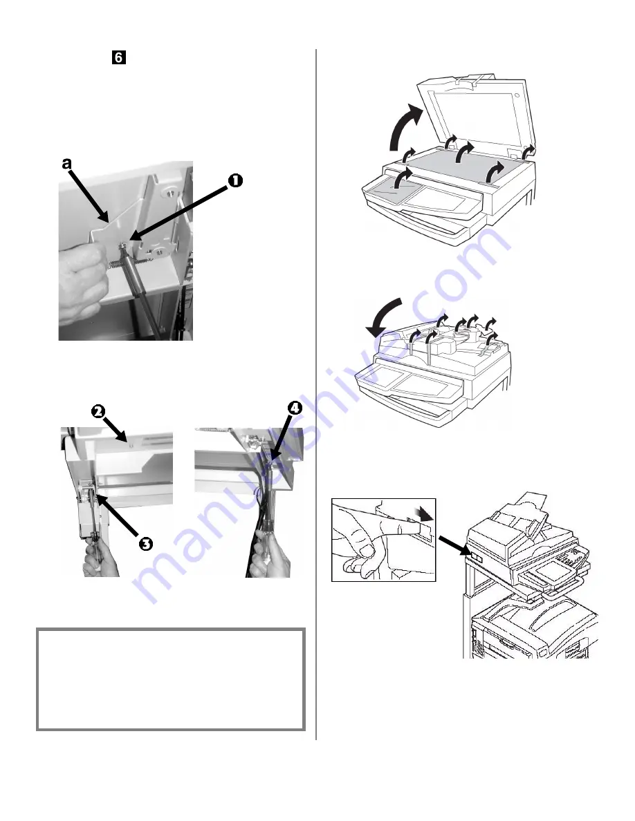
Fixez le scanneur à l’étagère avec les quatre vis 

moyennes 

: Voyez la « Accessoires dans la 

boîte du support » à la page 8

a.

Première vis : Tirez vers l’arrière le levier de 

sécurité (a) pour découvrir le trou dans 

l’étagère. Insérer une vis moyenne vers le haut 

à travers le trou et dans le scanneur, puis 

serrez la vis (1).

b.

Trois vis restantes : Procédez comme suit : 

avant gauche (2), arrière gauche (3) et arrière 

droit (4).

5.

Ouvrez le couvercle du scanneur et retirez tout 

matériau d’emballage.

6.

Fermez le couvercle du scanneur et retirez tout 

ruban d’expédition.

7.

Placez le verrou du scanneur (sur le côté gauche 

du scanneur) en position de déverrouillage 

(UNLOCK).

Important!

Pour déplacer le support du scanneur avec le 
scanneur fixé, vérifiez que le scanneur est fixé 
à la partie inférieure du support avec les 
quatre vis. N’inclinez pas le support car le 
dessus du scanneur pourrait faire basculer le 
poids du scanneur.

Summary of Contents for CX3641 MFP

Page 1: ......

Page 2: ...2 2 Do not begin installation of this device before reading this entire Installation Guide Important safety warnings follow CX3641 MFP Warning Icon jpg...

Page 3: ...3 Overview CX3641 MFP Configuration A is shipped in four units 1 Printer 2 High capacity Feeder 3 Scanner 4 Stand CX3641 MFP...

Page 4: ...anner on the Stand and Secure it to the Shelf Step 5 Make the Scanner Connections Step 6 Attach the Printer to the Stand Step 7 Finish the Installation Step 8 Connect to the Network Step 9 Install the...

Page 5: ...e HCF 4 Lift the printer onto the HCF aligning the holes on the bottom of the printer with the pins on the HCF 5 Go to Step 2 Prepare the Printer on page 6 Accessories in Printer Box Paper Catcher 4 C...

Page 6: ...e paper guides and move them apart c Remove the brightly colored shipping restraint d Set the guides a b for the paper size and load paper Note The default is letter size long edge feed e Close the tr...

Page 7: ...panel open the front cover and remove the shipping tape Close the front cover 5 Remove the colored image drum packing pieces 6 For each drum remove the tape and the protective sheets 7 Remove locks an...

Page 8: ...oner b Remove sealing tape and insert the cartridge into the corresponding color drum in the printer c Lock the toner cartridge with the lever 9 Close the top cover 10 Remove the backing from the stri...

Page 9: ...th Lock Washers and Flat Washers for Bottom of Printer Brackets 2 Thumb Screws for attaching the Printer to the Bumper Brackets 4 Small Screws with Lock Washers and Flat Washers for Top of Printer Bra...

Page 10: ...caution when assembling the stand NEVER ATTEMPT TO RAISE OR LOWER THE SHELF WITHOUT THE SCANNER BOLTED TO IT Without the weight of the scanner on it the shelf could rise rapidly when released potenti...

Page 11: ...e stand using the medium screws two per bracket 4 Unpack the plate lock mechanism 5 Place the scanner shelf on the frame and secure it in place using four of the medium screws and install the two rubb...

Page 12: ...lf cables facing the outer side wall and begin to feed it into the channel between the walls 7 Pull the safety lever 1 back and hold it while feeding the plate 2 through the channel Important Make sur...

Page 13: ...the handle key 4 inside the shelf 9 Rotate the release handle back and forth while moving the hole in the plate lock until the handle key 1 is firmly seated in the hole 10 Secure the plate lock mecha...

Page 14: ...f making sure the foot on the right front of the scanner engages the release plate 1 on the shelf Accessories in Scanner Box Data Control and Display DCD Cable Locking Cap Power Supply for Scanner 4 F...

Page 15: ...crews Attach as follows left front 2 left rear 3 and right rear 4 5 Open the scanner lid and remove all packing materials 6 Close the scanner lid and remove all the shipping tape 7 Slide the scanner l...

Page 16: ...the front of the scanner stand using the two screws provided in the printer box 2 Attach the scanner power supply see Accessories in Scanner Box on page 14 to the keyhole inside the back of the stand...

Page 17: ...and Box on page 9 6 Route the cables neatly as show below 7 Use the tie wraps to attach the scanner power supply cable to the DCD cable in two places The first tie wrap should be 8 inches from the top...

Page 18: ...ccessories in the Stand Box on page 9 2 Connect the printer power cord supplied in the printer box to the printer CX3641 MFP Be sure to use the 15A AC power cord supplied with the printer Use of a pow...

Page 19: ...ories in the Stand Box on page 9 6 Attach cables a Uncoil the DCD cable and mount the ferrite cores on each line see 3 and 4 below Cable and ferrite cores are supplied in the scanner box Accessories i...

Page 20: ...place b Place the open core about 1 inch from the cable connector on the printer end c Press the two halves of the core together until they click shut TO PREVENT ANY POSSIBLE CRUSHING OF FINGERS KEEP...

Page 21: ...on the control panel 2 Press the down arrow to select Print Information Press Enter 3 Press the down arrow to select Network Press Enter 4 Execute appears Press Enter Keep these sheets handy they cont...

Page 22: ...e OKI C3641MFP PS icon 3 Click Properties 4 Click the Installable Options tab 5 Select Two Way Communications 6 Type the Fiery IP address or DNS name 7 To display the printer s current default setting...

Page 23: ...e OS folder 7 Follow the on screen instructions 8 Select any utilities you want to install Click Install Add the Printer 1 Run the Print Center or Print Setup Utility Click Add 2 Click More Printers 3...

Page 24: ...asonable efforts have been made to make this document as accurate and helpful as possible we make no warranty of any kind expressed or implied as to the accuracy or completeness of the information con...

Page 25: ...Guide d installation du technicien Ne commencez pas l installation de cet appareil avoir d avoir lu tout ce guide d installation Avertissement important concernant la s curit ci apr s CX3641 MFP Warni...

Page 26: ...2 Sommaire La configuration A de l appareil CX3641 MFP est exp di e en quatre unit s 1 Imprimante 2 Alimentateur haute capacit 3 Scanneur 4 Support CX3641 MFP...

Page 27: ...upport tape 4 Installation du scanneur sur le support et fixation l tag re tape 5 R alisation des connexions du scanneur tape 6 Fixation de l imprimante au support tape 7 Fin de l installation tape 8...

Page 28: ...cez la sur l alimentateur haute capacit en alignant les orifices du dessous de l imprimante avec les tiges de l alimentateur 5 Passez l tape 2 Pr paration de l imprimante la page 5 Accessoires dans la...

Page 29: ...de l autre c Retirez le dispositif de blocage de couleur voyante d R glez les guides a b pour le format de papier et chargez du papier Remarque Le format par d faut est lettre alimentation par le c t...

Page 30: ...t et retirez le ruban d exp dition Fermez le capot avant 5 Retirez toute pi ce d emballage color e du tambour d image 6 Pour chaque tambour retirez le ruban et les feuilles de protection 7 Retirez les...

Page 31: ...ruban de scellement et ins rez la cartouche dans le tambour d image couleur correspondant dans l imprimante c Verrouillez la cartouche de toner en place l aide du levier 9 Fermez le capot sup rieur 10...

Page 32: ...pour le bas des supports de fixation d imprimante 2 vis ailettes pour fixer l imprimante aux supports de fixation du pare chocs 4 petites vis avec rondelles de blocage et rondelles plates pour le haut...

Page 33: ...tes tr s attention pendant l assemblage du support NE TENTEZ JAMAIS DE MONTER OU D ABAISSER L TAG RE SANS QUE LE SCANNEUR NE SOIT BOULONN CELLE CI Sans le poids du scanneur sur celle ci l tag re peut...

Page 34: ...au support avec les vis moyennes deux par support de fixation 4 D ballez le verrou de plaque 5 Placez l tag re du scanner sur le ch ssis et fixez le en place avec quatre des vis de longueur moyenne e...

Page 35: ...bles face la paroi ext rieure et commencez le faire passer dans la rainure entre les parois 7 Tirez le levier de s curit 1 vers l arri re et tenez le tout en faisant passer la plaque 2 dans la rainur...

Page 36: ...s la cl de poign e 4 l int rieur de l tag re 9 Faites tourner la poign e de d verrouillage d avant en arri re tout en d pla ant le trou dans le verrou de plaque jusqu ce que la cl de poign e 1 soit bi...

Page 37: ...le pied l avant droit du scanneur entre dans la plaque de d verrouillage 1 sur l tag re Accessoires dans la bo te du scanneur C ble de donn es de contr le et d affichage DCD Bouchon d arr t Bloc d ali...

Page 38: ...suit avant gauche 2 arri re gauche 3 et arri re droit 4 5 Ouvrez le couvercle du scanneur et retirez tout mat riau d emballage 6 Fermez le couvercle du scanneur et retirez tout ruban d exp dition 7 Pl...

Page 39: ...l avant du support du scanneur avec les deux vis livr es dans la bo te de l imprimante 2 Fixez l alimentation lectrique du scanneur voir Accessoires dans la bo te du scanneur la page 13 l ouverture e...

Page 40: ...page 8 6 Acheminez proprement les c bles comme illustr ci dessous 7 Utilisez les attaches pour fixer le c ble d alimentation du scanneur au c ble DCD en deux endroits La premi re attache devra tre 8 p...

Page 41: ...on voir Accessoires dans la bo te du support la page 8 2 Branchez le cordon d alimentation de l imprimante livr dans la bo te de l imprimante l imprimante CX3641 MFP Utilisez le cordon d alimentation...

Page 42: ...s dans la bo te du support la page 8 6 Fixez les c bles a D roulez le c ble DCD et montez les tores magn tiques sur chaque fil voir 3 et 4 ci dessous Les c ble et les tores magn tiques sont livr es da...

Page 43: ...agn tique en place b Placez la tore magn tique ouverte environ 1 po du connecteur de c ble c t imprimante c Appuyez sur les deux moiti s de tore jusqu ce qu elles s enclenchent POUR VITER TOUT CRASEME...

Page 44: ...ui qui correspond vos besoins Cependant chacun des pilotes doit tre install individuellement Windows Configuration de r seau Imprimez la page Network Information 1 Appuyez sur Menu sur le tableau de c...

Page 45: ...MFP User Guide Installation des utilitaires Fiery EFI 1 Ins rez le CD2 dans l unit de CD ROM 2 S lectionnez votre langue 3 Acceptez le contrat de licence 4 S lectionnez l application EFI que vous voul...

Page 46: ...c de papier en option de l unit duplex recto verso du disque dur ou de m moire suppl mentaire vous devez acc der au pilote et les activer 1 Cliquez sur D marrer Param tres Imprimantes et t l copieurs...

Page 47: ...work et Maintenance sur la page Web Note La page Web ne peut tre affich e que lorsque l imprimante est connect e au r seau Installation des utilitaires Fiery EFI 1 Ins rez le CD3 dans l unit de CD ROM...

Page 48: ...raisonnables aient t faits pour rendre ce document aussi pr cis et utile que possible nous n offrons aucune garantie quelle qu elle soit expresse ou implicite relativement l exactitude et l int grit d...

Reviews: