CHAPTER 4 TESTING
Ohaus Corporation www.ohaus.com
4-2 3000 Series T32ME & MC Indicators Service Manual
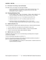
4.4 Performance Tests Using a Load Cell Simulator
A simulator can be used in place of a scale base if available.
– Connect the simulator to Terminal Block J7 (the Load Cell terminal block) on the
PCB, so that EX+, EX–, S+ and S– are matched at each end of the cable.
(See Figures 1-2 and 1-3, page 1-4.)
4.4.1 Overload/Underload Test
1. Set the simulator to zero. Power on the Indicator. Perform a Span Calibration, with
zero at the simulator’s 0.2 setting, and 100% capacity at the 1.8 mv/V setting.
2. Adjust the simulator to zero mv/V. The indicator should show Error 8.4.
3. Adjust the simulator to 2.0 mv/V. The indicator should show Error 8.3.
4. Adjust the simulator to each setting between 0.2 mv/V and 1.8 mv/V.
The indicator reading should be stable and linear throughout the range of settings.
4.5 Calibration Retention Test
This test checks that the Indicator retains calibration after power is removed and then restored.
5. Turn the Indicator OFF and disconnect the AC Adapter or power cord.
6. Wait one minute, then reconnect the AC Adapter or power cord to the Indicator.
7.
Check to insure that the Indicator retained calibration settings.
4.6 RS232 Interface Test / Print Test
The RS232 Interface performance can be monitored using an external printer or computer
connected to the Indicator.
To set up communication parameters, see Section 1.8.
Once the communications parameters match between the Indicator and either a computer or
printer, it is possible to test the Indicator’s print function.
–
Press the
Print/Units
button. Printing to an external printer or computer should occur
each time the button is pressed.
Summary of Contents for T32ME
Page 2: ......
Page 4: ......
Page 45: ......
Page 46: ...80253153 P N 80253153 SERVICE MANUAL 3000 SERIES T32MC T32ME INDICATORS...


