CHAPTER 3 REPAIR PROCEDURES
3000 Series T32ME & MC Indicators Service Manual
3-5
Ohaus Corporation www.ohaus.com
3.3.2.2 How Strain Gauge Load Cells Operate
continued
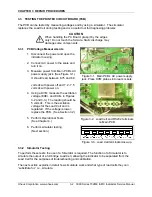
Figure 3-10 shows a typical Load Cell wiring scheme for an indicator.
Note
that some weighing units
do not
have Sense connectors
.
When they do, they also have
Sense Jumpers (W1 and W2 in Figure 7), which must be shorted if the load cell does not have
Sense wires to connect to the terminal.
The “Shield” terminal is often labeled “GND” (Ground), but its function is to shield current to or
from the other connectors, to ensure accurate measuring results.
Figure 3-10. T32ME/MC Indicator Printed Circuit Board (PCB).
Figure 3-11. Load Cell wiring.
3.3.2.3 How to Operate Simulators
The function of a Simulator is to simulate the output of a full bridge Load Cell, allowing the scale
to be separated from the Load Cell for the purposes of troubleshooting and calibration. A typical
Ohaus Load Cell is rated at 2mV/V output with a 5-Volt excitation voltage applied. (These
values vary for specific models.)
3.3.2.4 How to Attach a Simulator
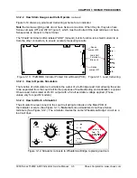
The simulator’s wires connect to the Load Cell wiring terminals on the Main PCB of
the indicator or scale. (See Figure 3-11.)
Note
that some simulators do not have Sense
terminals. (See Figure 3-12.) The simulator creates the same “Wheatstone Bridge” circuit as a
load cell does.
Figure 3-12. Simulator connects to Wheatstone Bridge, replacing load cell.
Sense
Jumper W2
Load Cell
Terminal
Block J5
Sense
Jumper W1
Summary of Contents for T32ME
Page 2: ......
Page 4: ......
Page 45: ......
Page 46: ...80253153 P N 80253153 SERVICE MANUAL 3000 SERIES T32MC T32ME INDICATORS...


