UNPACKING AND SET-UP (Cont.)
7. Place the Scale Plate on the four vertical Support Posts, with the solid weld
stud resting on the left front Post (with the two Lock Nuts). Hook the mass
Hanger Assembly on the Ring that is located at the right end of the Beam.
8. Unpack the Slotted Masses from the corrugated box and place them on the
Mass Rack.
USING THE BALANCE (ZEROING)
1. Move all four Poises to their ZERO positions at
the extreme left end of travel. The Rear Poise is
equipped with a pin that will position it
accurately in the notches.
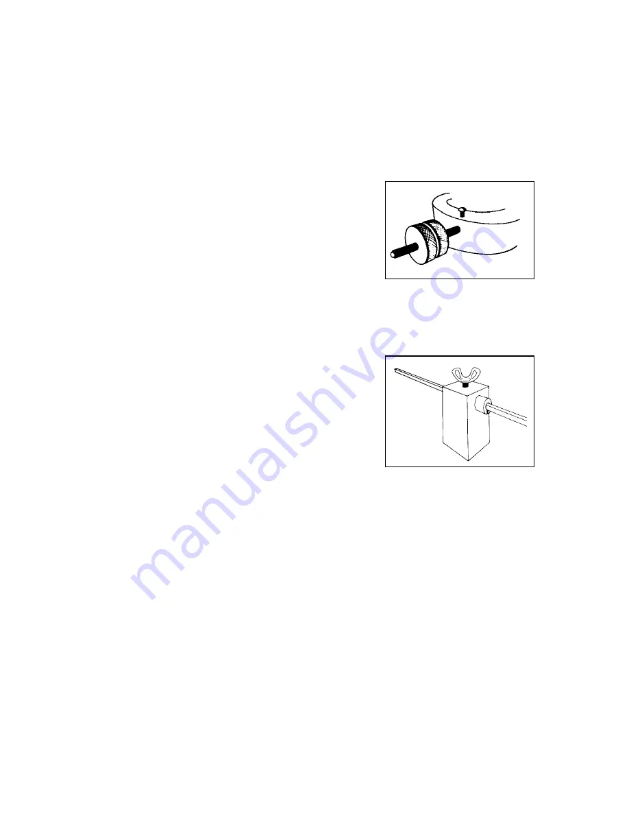
2. If the Balance does not come to rest exactly at
zero, it can be rebalanced by using the two
knurled, brass Adjustment Nuts of the Balance
Compensator Assembly. When correct balance
has been restored, be sure to lock the Balance
Nuts against each other to prevent movement.
Balance Compressor
WEIGHING
Net Weight can be determined rapidly by following
these steps:
1. Counterbalance the EMPTY container with the
two Tare Poises. Loosen the Thumb Screw of
the larger Tare Poise and move both Poises to
the right. The larger Tare Poise is used for
COARSE
balancing and then is locked with the
thumb screw. The smaller Tare Poise is used
for
FINE
balancing. It is spring-loaded to protect
against accidental movement.
Tare Poise
2. Place the specimen as near the center of the Scale Plate as possible.
3. Move the Rear Poise to the right until it is in the first notch that will cause the
Beam to DROP below the Balance Indicator at the pointer end of the beam.
Move it to the left one notch and the Beam will RISE.
4. Move the Front Poise to the right until balance is obtained.
5. Read the weight of the specimen directly by adding the values indicated by
the Poises.
6. If the Rear Poise can be moved to the extreme right notch but it does not
cause the Beam to DROP, return both the Front and Rear Poises to ZERO
and add Slotted Attachment Masses to the Mass Hanger Assembly. Add
sufficient masses to cause the Beam to DROP below the Balance Indicator
at the pointer end of the Beam. Remove the smallest (lightest) mass and
follow Steps 3, 4 and 5. Add the total value of the Attachment Masses on
the Mass Hanger Assembly to the values indicated by the positions of the
two poises to obtain weight of the specimen.


