background image


B

B

C

C

H

H

6

6

1

1

0

0


M

M

o

o

w

w

e

e

r

r


C

C

a

a

r

r

r

r

i

i

e

e

r

r


A

A

s

s

s

s

e

e

m

m

b

b

l

l

y

y


I

I

n

n

s

s

t

t

r

r

u

u

c

c

t

t

i

i

o

o

n

n

s

s


CAUTION: Wear proper protective equipment such as Safety  

Glasses and protective shoes when assembling. 


Lay out all parts so location and verification will be easier.  Make sure all parts were received 

before proceeding with the assembly.   


Install the two Tire and Wheel Assemblies onto the Hub Assemblies and properly tighten Lug 

Bolts or Lug Nuts. 


Attach the Tongue Jack to the Main Frame Weldment and secure in place with the Locking Pin. 


Attach the Driveshaft Support Weldment to the Main Frame using six 1/2” x 1 ½”” Capscrews, 

Lockwashers and Hex Nuts.  If the Spline Shaft  and Flange Bearings are not installed in the 

Driveshaft Support, do so at this time using four ½” x 4 1/2” Hex Capscrews, Lockwashers and 

Hex Nuts.  Mount the Flange Bearings with the Grease Zerks toward the bottom.  Install the 

Spline Shaft with 5” of shaft between the bearing flange and the end of the shaft protruding on 

the  backside.  After inserting the Spline Shaft into the Flange Bearings, be sure to lock the 

eccentric lock collars on both Flange Bearings.  Standing at the rear of the Mower Carrier and 

facing forward, lock both collars in a clockwise direction and tighten the setcrews. 


Install the two Driveline Shields using eight 3/8” x 1” Hex Capscrews, Lockwashers and Hex 

Nuts. 


Summary of Contents for BCH610

Page 1: ...IM MP PO OR RT TA AN NT T The Mower Carrier is designed to operate with Disc Mowers up to 10 in size In order to insure safe operation it may be necessary to install the optional Weight Box for additional counter balance W WA AR RN NI IN NG G DO NOT DISCONNECT MOWER CARRIER FROM TRACTOR UNLESS MOWER CUTTERBAR IS LOWERED TO THE GROUND O Og gd de en n M Me et ta al lw wo or rk ks s I In nc c 301 N M...

Page 2: ......

Page 3: ... of Contents Page 2 Introduction Page 3 Safety Page 4 Decals Page 5 Assembly Instructions Page 8 Attaching Mower Page 9 Operation Page 10 Transport Page 11 Maintenance Page 12 Mower Carrier Parts List Page 15 Warranty Card ...

Page 4: ...amage or excessive wear to other parts The manufacturer reserves the right to make improvements discontinue or change specifications models or design without notice and without incurring obligation When ordering parts for your Mower Carrier please specify the part number and the part description as shown in the parts listing in this manual Please give the serial number of the Disc Mower Carrier in...

Page 5: ...e starting All bystanders should be a safe distance from the machine when in operation High pressure oil leaks can penetrate skin causing serious injury Do not use your finger or other skin to check for leaks Disengage PTO apply parking brake and stop tractor engine before dismounting tractor Keep hands feet and clothing away from moving parts Never transport faster than surface conditions allow D...

Page 6: ...ortant Many of the following Decals are located on your Disc Mower Carrier Before you operate the Disc Mower Carrier read and understand the purpose for each Decal Replace any damaged Decals Keep all Decals clear and readable ...

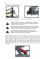
Page 7: ...pport Weldment to the Main Frame using six 1 2 x 1 Capscrews Lockwashers and Hex Nuts If the Spline Shaft and Flange Bearings are not installed in the Driveshaft Support do so at this time using four x 4 1 2 Hex Capscrews Lockwashers and Hex Nuts Mount the Flange Bearings with the Grease Zerks toward the bottom Install the Spline Shaft with 5 of shaft between the bearing flange and the end of the ...

Page 8: ...tem could result in injury when the mower falls abruptly Mount the Hydraulic Cylinder on the Carrier and install two NPT Male x 3 8 JIC Male Elbows in the Hydraulic Cylinder Note Do not use Teflon tape only use liquid type thread sealant Attach the 114 Hose with NPT Male 3 8 JIC Swivel ends to the front port of the Hydraulic Cylinder Attach the 122 Hose with NPT Male 3 8 JIC Swivel ends to the rea...

Page 9: ...rame and Mower Carrier parallel with the ground After the Tractor Drawbar and the Mower Carrier Clevis Hitch are properly adjusted the Tractor and Mower Carrier can be hitched together WARNING Do not disconnect Mower Carrier from Tractor unless Cutterbar is lowered to the ground D Dr ri iv ve el li in ne e When attaching a Mower to the Mower Carrier the original Mower Driveline will be used betwee...

Page 10: ...ism cords so they reach the tractor cab B Be ef fo or re e O Op pe er ra at ti in ng g Attach the Mower PTO Driveline between the Tractor and Mower Carrier Attach the PTO Driveline that came with the Mower Carrier between the Mower Carrier and the Mower CAUTION When attaching the PTO Driveline make sure that the Yoke is properly locked on the shaft WARNING Operate only with 540 RPM PTO Connect the...

Page 11: ...ge or heavy Disc Mower CAUTION Do not operate the Mower Carrier without sufficient counter balance to prevent a rollover O Op pe er ra at ti io on n O Op pe er ra at ti in ng g I In ns st tr ru uc ct ti io on ns s The PTO Operating Speed for the Mower Carrier is 540 RPM Do not over speed Many factors can determine the proper ground speed such as ground conditions density humidity and type of forag...

Page 12: ...end beyond the Tractor tires Make sure the Cutter Bar is locked and secured for transporting WARNING Always use the Tractor Warning Lights SMV Emblem and Reflectors for adequate warning to operators of other vehicles M Ma ai in nt te en na an nc ce e Grease all Drivelines Bearings and Grease Zerks daily to ensure proper operation Periodically check all Bolts and Nuts for tightness Periodically che...

Page 13: ...11 Notes ...

Page 14: ...12 ...

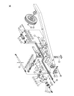
Page 15: ...122 Elbow 3 8 JIC M x MP 2 19 OE 302 Pipe Coupler Female 1 20 0 57 Flow Restrictor NPT 1 32 1 21 MC124 Grease Seal 1 22 MC125 Inner Bearing 2 23 MC126 Wheel Hub 2 24 MC127 Outer Bearing 2 25 MC128 Flatwasher 2 26 MC129 Castle Nut 2 27 MC130 Cotter Pin 2 28 MC131 Hub Cap 2 29 MC135 Lug Bolt 12 30 MC103 Tire Wheel Assembly 2 31 0 157 Hex Capscrew 3 8 x 1 GR5 2 32 MCH38F Flatwasher 3 8 4 33 NL38 Nylo...

Page 16: ...14 Notes ...

Page 17: ...Inc reserves the right to request the return of any part in question to be sent to the factory for inspection All returned parts must be sent to the factory freight prepaid This warranty is extended solely to the original purchaser and is not transferable This warranty is not valid unless the warranty card has been returned to Ogden Metalworks Inc within 30 days from the date of purchase by the en...

Page 18: ......

Page 19: ......
Reviews: