background image

37390
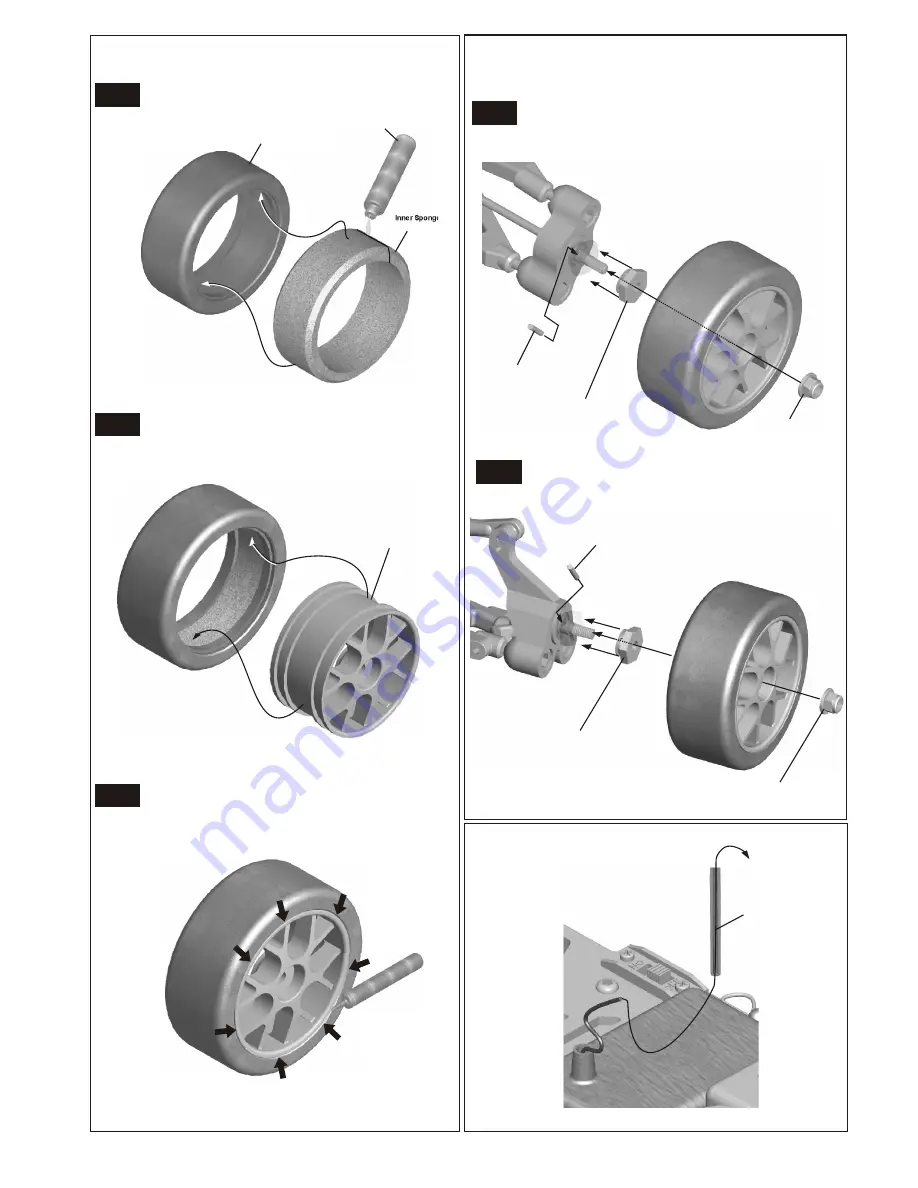
2x 10.8 mm pin

37390
2x 10.8 mm pin

Driver Nut

Driver Nut

4mm
Nylon Nut

4mm
Nylon Nut

Antenna pipe

Inner Sponge

Super Glue

*Insert the inner Sponge before
assembly.

*Insert the inner Sponge before
 assembly.

*Insert wheel into tire.

(FRONT ASSEMBLY)

(REAR  ASSEMBLY)

Radial Body

ASSEMBLY OF THE TIRES AND WHEELS

ASSEMBLY OF THE WHEELS ONTO FRONT
KNUCKLE ARM AND REAR HUB

PLUG ANTENNA PIPE INTO ANTENNA POST

Step 1

Step 1

Step 2

Step 2

Step 3

87660

87610 -White

“Y” Spoke Wheel

37590 - PLASTIC

37590 - PLASTIC

38328 - Alum. W/ Oring

38328 - Alum. W/ Oring

10986

10986

30560

*Apply instant cement.

MOLDED FOAM INSERTS
87658 - BLUE
87659 - YELLOW

(FRONT)

(REAR)

+

+

+

+

-

-

-

-

SETTING GUIDE

FRONT AND REAR
TOE- IN AND TOE- OUT SETTING

FRONT AND REAR CAMBER ANGLE SETTING

Note: Place the model car on a flat surface . Raise the chassis to it's
           maximum clearance before the wheels leave the ground.
           Adjust length of the front and rear lower ball so that the wheels
           are at  right angles  to the ground.
           

Adjust the length of front steering rod to change the
toe angle.

Making the steering rod longer will make the front tires toe-in.
Response will be slower and will over steer. 
Making  the steering rod shorter will make the front tires toe-out.
Response will be quicker and will under steer.

We recommended adjust the front toe-out in 1.5 degree.


Adjust  the  length of the rear hub (8mm ball) to change 
the toe angle.
Making  the 8mm ball longer will make the rear tires toe-in.
Response will be under steer.
Making  the 8mm ball shorter will make the rear tires toe-out.
Response will be over steer.   

We recommended adjust the rear toe-in is 2 degree.

The front camber adjustment can be made by moving the 8mm
steering ball at the front upper arms on knuckles, clockwise or 
counter-clockwise.
We suggest using 1.5 degree of negative camber for the rear.

Rear 
Toe-In

Rear 
Toe-In

* Use 2.5mm hex wrench 
   to adjust upper arm ball
   in front.

 Adjust the length of the turnbuckle on
 can be change the rear camber.
 We suggest using 2 degree of negative camber for the rear.

 the rear upper arms

Turnbuckle

Toe-Out

Toe-Out

Toe-In

Neutral Position

* Use a 2.5mm allen wrench to adjust toe-in for front and rear. 

2.5mm Allen 
Wrench

Front 
Steering Rod

Positive

Positive

Positive

Positive

Negative

Negative

Negative

Negative

* Use a  tool  to adjust the 
   length of


rear upper arms .  

 the turnbuckle

   on the 

Summary of Contents for LD-3 PRO VERSION

Page 1: ...model You are responsible for this models assembly and safe operation Always keep this instruction manual ready at hand for quick reference even after completing the assembly SPECIFICATION ARE SUBJEC...

Page 2: ...educed The best is to use a 5 cell hump pack for increased voltage Recommended Option You may want to upgrade the car battery pack to a Ni Cad or NiHm 5 cell type 600AE This will give more run time OF...

Page 3: ...healthy off Fuel contains Methanol and Nitro Methane and is flammable and poisonous Glow Fuel Glow fuel is poisonous Store fuel in cool ventilated location Refer the glow fuel Glow fuel is flammable...

Page 4: ...Gear Large 13T Diff Gear 13T Diff Gear Large Large Step 1 Step 3 Step 4 Step 1 Step 2 10x15x4mm Bearing 5x11x4mm Ball Bearing 5x11x4mm 5x11x4mm Ball Bearing Ball Bearing Gear case Cap Joint Large Bev...

Page 5: ...12mm Screw 94004 Screw 94004 M2 6X10mm Screw 94050 M2 6X10mm M2 6X10mm Screw 94050 Screw 94050 Gear Case Gear Case 38251 38251 ASSEMBLY OF THE FRONT GEAR BOX Build a gear box for front The gear box af...

Page 6: ...ring Spring M2x10mm Screw M2x10mm Screw M2x10mm Screw Metal Ball Metal Ball Clutch Shoe Clutch Shoe SCREW AS SHOWN LEVEL WITH HOLE EDGE SCREW AS SHOWN LEVEL WITH HOLE EDGE SET BALL TO REST ON CAM NOT...

Page 7: ...M3x4mm screw 38321 M3x4mm screw 2x8 8mm Pin 2x8 8mm Pin 3x14 8mm 3x14 8mm Pin Pin 5x8x0 8mm Washer 5x8mm Washer 5x11x4mm 5x11x4mm Ball Bearing Ball Bearing 5x11x4mm Ball Bearing 5x11x4mm Ball Bearing...

Page 8: ...crew Spring 40044 38271 38271 38289 38289 38273 38289 38289 40044 38272 38272 Take off the double sided tape before assembly Brake Pad Brake Pad Brake Pad Linings Brake Pad Linings 1 1 2 2 Bulk Head c...

Page 9: ...M2 6x10mm 94050 M2 6x10mm Screw Screw Screw Screw Screw Screw 5x11x4mm Ball Bearing Gear box Gear box DIFFERENTIAL ASSEMBLY Add Gear Grease before closing gear case 38254 38254 37430 38251 38251 12x1...

Page 10: ...g Ball 8mm Steering Ball Washer 39150 39150 38265 38265 37430 37430 37450 37450 39190 39140 39140 39141 L make are for left side Make steering ball move smooth Assembly of the right and left side are...

Page 11: ...m Set Screw 3x8 mm Set Screw 94004 M3x12 mm Screw 94004 M3x12 mm Screw M3x12 mm Screw 6 mm Ball and Socket 6 mm Ball Socket 6 mm Ball Socket REAR UPPER ARM 37100 37100 37100 37100 37210 37210 37370 37...

Page 12: ...ft and right hand side Steering Servo Rod 37650 4mm Ball End 94003 M3x10mm Screw 94004 M3x12mm Screw 94004 M3x12mm Screw 94004 M3x12mm Screw 94004 M3x12mm Screw Servo Saver Spring Servo Saver Spring S...

Page 13: ...Head Hex Screw 94019 M3x10mm Flat Head Hex Screw M3x10mm Flat Head Hex Screw 94018 M3x5mm Flat Head HexScrew M3x10mm Flat Head Hex Screw M3x10mm Flat Screw 37360 4mm Ball Socket 37360 4mm Ball Socket...

Page 14: ...Screw 94019 M3x10mm Flat Head Hex Screw 94019 M3x10mm Flat Head Hex Screw 94024 M3x30mm Flat Screw 94024 M3x30mm Flat Head Hex Screw 94019 M3x10mm Flat Screw 50mm Lower Arm Shaft 51mm Lower Arm Shaft...

Page 15: ...ering Servo Servo Post Servo Post Servo Adapter Servo Adapter Sevro Post Radio Tray 37360 4mm Ball Socket 10768 Steering Servo Horn 10769 Servo Horn Adapter THROTTLE SERVO A A Use the screw provided f...

Page 16: ...Head Screw 94019 M3x10mm Flat Head Screw 94019 M3x10mm Flat Head Screw 94002 M3x8mm Screw 94002 M3x8mm Screw 94002 M3x8mm Screw 94002 M3x8mm Screw 94002 M3x8mm Screw 94002 M3x8mm Screw 94002 M3x8mm Sc...

Page 17: ...12mm Screw 94006 M3x18mm Screw 94006 M3x18mm Screw 6mm Ball Socket 6mm Ball Socket 90020 2 5mm E Ring 90020 2 5mm E Ring 90020 2 5mm E Ring Shock Tower Caster Angle Adjuster 1 5mm Shock Tower Front Up...

Page 18: ...mm Ball Bearing 5x8x2 5mm Ball Bearing 5x8mm Ball Bearing 94041 M3 Nylon Nut 3X8 mm Washer 3X8 mm Washer M3x5mm Screw M3x5mm Screw Clutch Bell 20T 2nd Clutch Gear 16T 1st Clutch Gear Put the 35958 bef...

Page 19: ...TO ENGINE MOUNT ASSEMBLY OF THE MANIFOLD Manifold Gasket 38286 Side Exhaust Manifold Put the nylon nut into the groove of the engine mount 38150 Engine Mount 38162 Use the note book paper to set gear...

Page 20: ...um Stopper 3x3mm Set Screw 3x3mm Set Screw 3x3mm Set Screw 94033 3x3mm Set Screw THROTTLE SERVO Brake Lever Screw 3x3mm Set Screw 2mm Rod Throttle Slider Throttle Rod Use the screw provided from your...

Page 21: ...k pressure nipple Connect to fuel nipple Connect to carbureter Connect to muffler pressure nipple ASSEMBLY OF THE MUFFLER ASSEMBLY OF THE FUEL TUBE AND PRESSURE TUBE INSTALLATION OF AIR FILTER Step 1...

Page 22: ...2mm E Ring 37967 C Ring 37100 Washer Block ASSEMBLY OF THE ALUMINUM THREADED BODY SHOCKS NOTE LEXAN SHOCK ASSEMBLY SEEAPPENDIX PAGES FlLLING THE SHOCKS WITH OIL ASSEMBLY OF THE FRONT SHOCK INTO SHOCK...

Page 23: ...crew Body Holder Body Pin 39320 37410 Insert body pins into body holder to the desired height 94002 M3x8mm Screw Body Post Rear Body Post Front Body Post Front Foam Bumper ASSEMBLY OF THE FRONT BUMPER...

Page 24: ...Insert wheel into tire FRONT ASSEMBLY REAR ASSEMBLY Radial Body ASSEMBLY OF THE TIRES AND WHEELS ASSEMBLY OF THE WHEELS ONTO FRONT KNUCKLE ARM AND REAR HUB PLUG ANTENNA PIPE INTO ANTENNA POST Step 1...

Page 25: ...he 8mm ball longer will make the rear tires toe in Response will be under steer Making the 8mm ball shorter will make the rear tires toe out Response will be over steer We recommended adjust the rear...

Page 26: ...n Carburetor at full throttle position Carburetor at full throttle position 2mm space 2mm space IN BRAKE POSITION IN BRAKE POSITION Carburetor at idle position Carburetor at idle position The spring s...

Page 27: ...r clockwise Loosen INSTRUCTIONS 38322 SPEED TRANSMISSION 2 SPEED GEAR RATIO COMBINATIONS 2 SPEED OPTION PARTS IMPORTANT The sum of the spur gear and clutch gear for1st gear must be equal Also he sum o...

Page 28: ......

Page 29: ...APPENDIX PAGES...

Page 30: ...ly moving piston up and down Pressure Top Cap 37100 Spring collar 37100 Spring tension adjust 37100 Ball end short Shock Spring Black Spring Holder 94045 2mm E Ring ASSEMBLY OF THE LEXAN RTR SHOCKS Fi...

Page 31: ...screw 2x8 8mmPin 3x14 8mm Pin 5x8mm 5x8mm 38333 44T Spur Gear 34700 2x8 8mm 5x8mm 2 5mm Bevel Gear 5x9mm 5x9mm 3x8mm M3x5mm Screw Washer Washer Pin 38334 Single Speed Shaft Washer E Ring 16T 38258 Was...

Page 32: ......

Reviews: