background image

OFITE, 11302 Steeplecrest Dr., Houston, TX 77065 USA / Tel: 832-320-7300 / Fax: 713-880-9886 / www.ofite.com

18

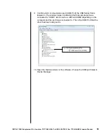
9. 

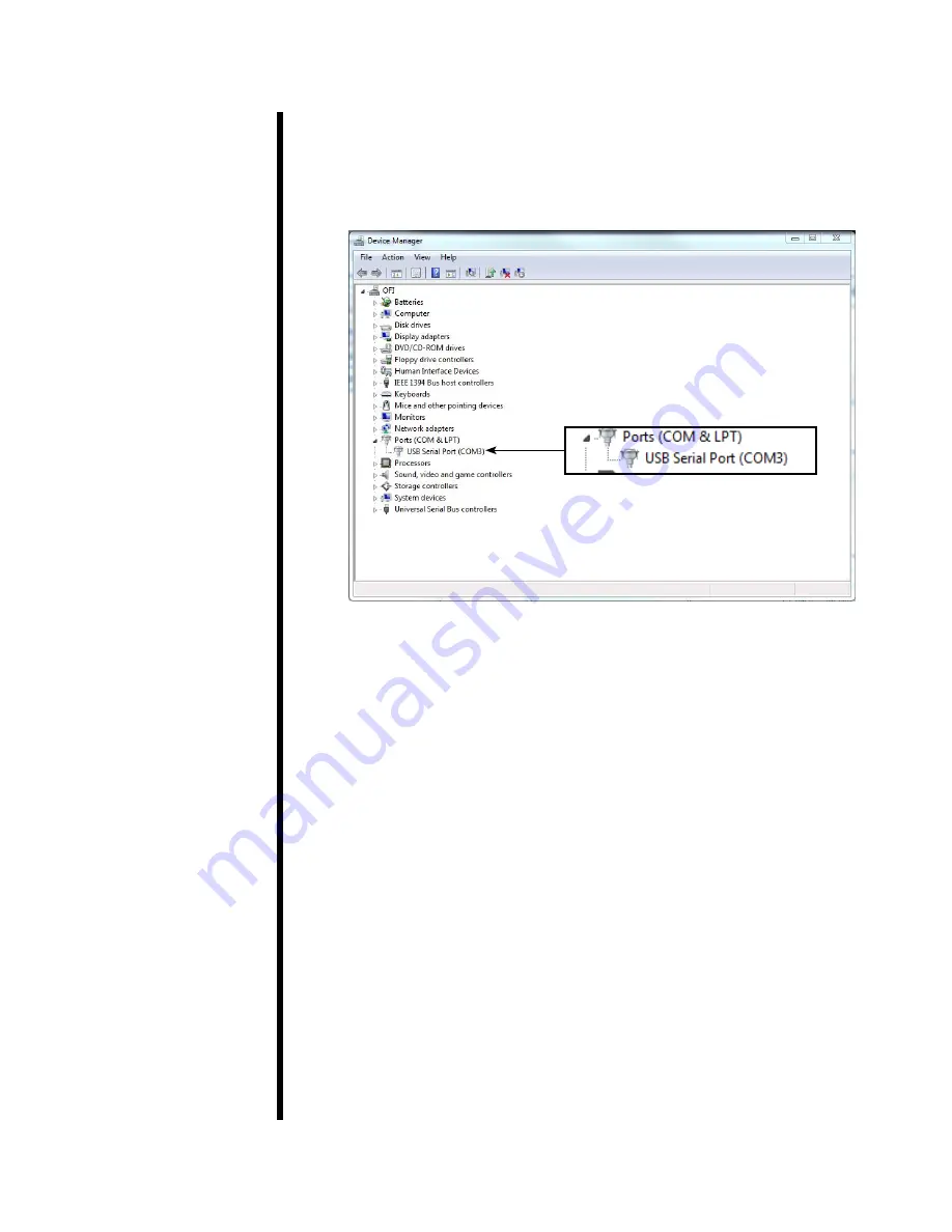
Confirm which communication port (COM Port) the USB Serial Port is 

located in. The window below is indicating that this sample port was 

connected to “COM3” which can be a different COM# depending on the 

computer and the port it was connected to. This is the COM Port that the 

driver has been assigned to.

10. Open the Options screen in the software. Choose the COM port listed in 

Device Manager.

Summary of Contents for 170-00-4S

Page 1: ...00 4S 115 VAC 170 00 4S 230 230 VAC 170 00 4S LC Load Cell Option Instruction Manual Updated 6 14 2019 Ver 6 OFI Testing Equipment Inc 11302 Steeplecrest Dr Houston Texas 77065 U S A Tele 832 320 7300 Fax 713 880 9886 www ofite com Copyright OFITE 2015 ...

Page 2: ...A Tel 832 320 7300 Fax 713 880 9886 www ofite com 1 Intro 2 Specifications 2 Components 2 Safety 3 Setup 4 Operation 5 Load Cell Option 11 Software Setup 12 Calibration 15 Appendix 16 Driver Install 16 Warranty and Return Policy 19 Table of Content ...

Page 3: ...elief Valve 130 81 028 Regulator 152 37 AC Power Cord 115 Volt 152 38 AC Power Cord 230 Volt 153 14 Graduated Cylinder 50 mL 1 mL Glass 170 06 1 Back Pressure Receiver 170 07 O ring for Receiver Body 170 19 Filter Paper Specially Hardened for Filter Presses 2 5 6 35 cm Diameter Box of 100 170 20 Manifold Block 170 93 Wrench for Valve Stem 171 45 7 Thermocouple 171 23 1 Safety Pin with Lanyard 174 ...

Page 4: ...t extreme care must be exercised at all times All safety precautions must be met especially in the cell breakdown procedure after the filtration procedure has been completed Cell Corrosion Test fluids under high tempreature and pressure can corrode the cell body and caps Carefully inspect the cell body and calls for corrosion before and after each test Some materials are more susceptible to corros...

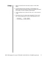
Page 5: ...Turn off both Main Power switches and all four Heat switches Make sure all regulators are backed off completely Turn them completely counterclockwise 3 Connect a Nitrogen source to the back of the unit The inlet connector is NPT 4 On the back of the unit is a power inlet configured for 115 VAC or 230 VAC Plug the supplied power cord into an appropriate power source 170 00 4S 115 VAC 50 60 Hz 170 0...

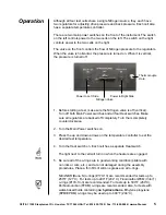
Page 6: ... Heat switches Make sure all regulators are backed off completely Turn them completely counterclockwise 2 Turn the Main Power switches on 3 Press the up and down arrows on the temperature controller to set the desired test temperature 4 Turn the Heat switch on Each cell has a separate Heat switch The light next to the cell will turn on when the heaters are engaged 5 Be sure all of the o rings are ...

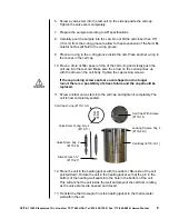
Page 7: ...the arrow on the cell body Tighten the cap locking screws If the cap locking screw seats are oval shaped and no longer round there is a possibility of stress failure and the cap should be replaced 11 Screw another valve stem into the cell cap and tighten it completely The cell is now completely sealed 12 Place the cell in the heating jacket with the outlet or filter side of the cell pointed down R...

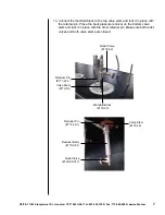
Page 8: ...n place with the retainer pin Place the back pressure receiver on the bottom valve stem and lock it in place with the other retainer pin Make sure both relief valves and both valve stems are closed Relief Valve 170 32 Manifold Block 170 20 Valve Stem 170 16 Retainer Pin 171 23 1 Retainer Pin 171 23 1 Valve Stem 170 16 Receiver Body 170 06 1 Relief Valve 120 85 017 ...

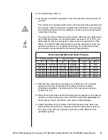
Page 9: ...s recommended for various test temperatures 17 Open the top valve stem by turning it one quarter turn This will add pressure to the test cell Maintain this pressure until the sample temperature stabilizes The heating time of the sample should never exceed one hour 18 When the fluid sample reaches the desired test temperature increase the pressure on the top pressure unit to 500 PSI 3 448 kPa more ...

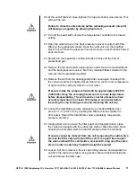
Page 10: ...r quick cool the cell by immersion in cool water Pressure inside the sample cell will still be approximately 500 PSI 3 450 kPa Keep the cell upright and cool it to room temperature before disassembling The cell must be cool for at least one hour at room temperature or at least 10 minutes in cool water before loosening the cap locking screws and removing the cell cap 26 Correct the total filtrate v...

Page 11: ...port the thickness of the filter cake to the nearest 1 32 0 8 mm 30 Clean and dry the apparatus thoroughly after each use Inspect and if necessary replace all of the o rings 31 After all testing is complete make sure all four heat switches are off the temperature controllers are set to 0 the regulators are backed off completely counterclockwise and both Main Power switches are off ...

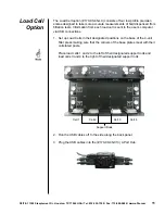
Page 12: ... is sent to the user s computer via USB connections 1 Set up Load Cells in their designated positions on the base of the 4 unit filter press making sure that the corners of the base plates meet with their correlated posts Place load cells 1 and 2 to the left of their designated support rods and load cells 3 and 4 to the right of their designated support rods 2 Run the USB cables off to the side al...

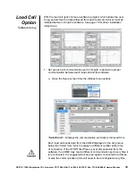
Page 13: ...t to determine proper communication between each load cell and the software a Open the Setup screen from the Utilities menu options Cell Com Displays the communication port data is retrieved from Each load cell sends data from the COM displayed in the drop menu below the Cell Com which is always a different number at the time of connection If the HTHP Filter Press is ever disconnected from the sof...

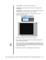
Page 14: ...en the Raw Data Analog screen in the Diagnostic menu to see responses from the comports 3 Select the first comport in Cell 1 Com shown on page 12 4 Place a weight on load cell 1 and look at the Raw Data Analog screen to see if it responds to the weight If there is no response continue selecting the remaining comports in Cell 1 Com until you find the comport that is responsive to the weight on that...

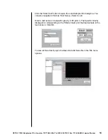
Page 15: ... Load Sample Info dialog box You can also navigate to this box Test Setup Select a cell Enter a test name and a specific gravity 1 00 g cm2 The Specific Gravity displayed is corresponding to the Filtrate Volume for that load sample in the main screen Click OK To view archived tests open the Open Data Archives file in the File menu options ...

Page 16: ... Enter the value of the weight in the 1st set weight g field and press the green arrow to display the Raw value 4 Add desired weight to the load cell 5 Enter the value of the weight in the 2nd set weight g field and press the green arrow to display the Raw value 6 Add desired weight to the load cell 7 Enter the value of the weight in the 3rd set weight g field and press the green arrow to display ...

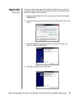
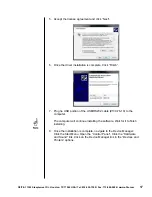
Page 17: ...ery HTHP Filter Press requires a driver to work with your PC before the software can be operated 1 Insert the software driver CD to the computer and select the file labeled CDM20828 exe 2 A prompt will open asking if you want to run this file Press Enter or click Run 3 The FTDI CDM Driver will open to allow you to extract the driver and launch the installer Click Extract 4 A welcome window will op...

Page 18: ...lete Click Finish 7 Plug he USB portion of the USB RS232 cable 130 76 19 to the computer The computer will continue installing the software Wait for it to finish installing 8 Once the installation is complete navigate to the Device Manager Click the Start Menu Open the Control Panel Click the Hardware and Sound link Click on the Device Manager link in the Devices and Printers options ...

Page 19: ...t the USB Serial Port is located in The window below is indicating that this sample port was connected to COM3 which can be a different COM depending on the computer and the port it was connected to This is the COM Port that the driver has been assigned to 10 Open the Options screen in the software Choose the COM port listed in Device Manager ...

Page 20: ...any losses or damages that occur as a result of Improper installation or maintenance of the products Misuse Neglect Adjustment by non authorized sources Improper environment Excessive or inadequate heating or air conditioning or electrical power failures surges or other irregularities Equipment products or material not manufactured by OFITE Firmware or hardware that have been modified or altered b...

Reviews: