background image

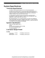
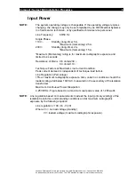
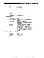
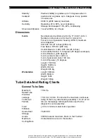
Compact / Series 7600 Installation Procedure

7

Radiography

1.5mm Focal Spot

High voltage range: 36 kVp to 110 kVp
Tube current 20 mA fixed.

Timer

Duration of radiography can be manually set
from 0.1sec to 4.0 sec with an internal electronic
timer.

Duty Cycle

110 kVp @ 20 mA maximum for 4.0 seconds.

Collimation

Nominal diameter iris circle for standard 9-inch
(22.8cm) system, continuously adjustable to less
than 5 x 5 cm, measured at the SID. A continuously
variable and rotatable slot collimator is
also standard.

Film Cassette

Standard: 10 x 12 x 5/8-inch nominal.

Holder

Metric: 24cm x 30cm

Accuracy

kVp: + 

10%

mA: + 

10%

Timer:

+ 10%

Video Signal

Composite video, EIA RS170A 60 Hz, 525 line, [International CCIR 50 Hz, 625
line] 1 Vp-p

Single "C" mounted FastScan flicker-free monitor

30cm (12 inch) Standard
44cm (17 inch) Optional
20 MHz bandwidth

Workstation

Dual Monitors 44cm (17”)
Fastscan, flicker-free monitor (100Hz) with anti reflection filter
Image Rotation: 360 degrees
400 Image Memory wih last image hold
X-Ray “ON” indicator lamp
Patient annotation keyboard and control panel for system operation
Integrated thermal printer (option)
Integrated multiformat camera 2-on-1 or 1-on-1 (option)

Environmental and Transport Requirements

Ambient 

Operating: 10 to 35 degrees C

Temperature

Extended

0 to 40 degrees C

Storage and
Transportation

Short-term

-10 to 55 degrees C

Storage and
Transportation

Used and Refurbished C-Arms are Available from www.SharpMedical.com - Call us at 800-969-9800 

An Independent C-Arm Service Provider.  This PDF provided for research / historical purposes only.

Summary of Contents for Compact Series

Page 1: ...879039 03 April 1997 OEC Medical Systems Inc 384 Wright Brothers Drive Salt Lake City UT 84116 Used and Refurbished C Arms are Available from www SharpMedical com Call us at 800 969 9800 An Independen...

Page 2: ...mpact Series 7600 Mobile Digital Imaging System only Refer to the Installation Report Checklist P N 00 879038 03 when installing a 7600 system Used and Refurbished C Arms are Available from www SharpM...

Page 3: ...ev B 02 July 1996 Added power supply tolerances kV tracking specifications and resolution specifications Rev C 03 April 1997 Add Series 7600 installation procedures Rev D 03 November 1998 Drawing chan...

Page 4: ...600 Installation Procedure iv Used and Refurbished C Arms are Available from www SharpMedical com Call us at 800 969 9800 An Independent C Arm Service Provider This PDF provided for research historica...

Page 5: ...ation 9 Unpacking and Inspection 10 Remove Protective Shipping Material 10 De pallet the System Compact 10 De pallet the System Series 10 C Arm 10 Workstation 10 Installation 11 Site Requirements 11 I...

Page 6: ...mage Tests 21 Radiographic Beam Alignment Test 21 Setup 21 Beam Alignment Verification 21 Complete Paper Work 22 Used and Refurbished C Arms are Available from www SharpMedical com Call us at 800 969...

Page 7: ...wing the documentation instructions included in the Field Service Documentation Package The OEC Medical Systems Inc Representative MUST sign the last page of the Installation Report and Checklist veri...

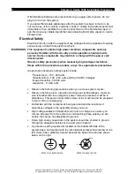
Page 8: ...High AC DC Voltages Image Intensifier 50 000 volts Generator 110 00 volts Observe the following precautions when you remove system covers Observe the two person rule when working near lethal voltages...

Page 9: ...requirements all users of these systems operators and service technicians must provide the QA Manager of OEC Medical Systems Inc with the following information regarding all reportable events as soon...

Page 10: ...licable manuals provided with those options OEC Medical Systems Inc will make available on request circuit diagrams component part lists descriptions calibration instructions or other information that...

Page 11: ...is independent of technique load factors Line Regulation Percentage 15 at maximum radiographic exposure Also under no conditions should the loaded voltage fall below 100 VAC measured on the secondary...

Page 12: ...e Anatomy 6 mA maximum continuous Snapshot 8 mA Duty Cycle 110 kVp 6 mA maximum continuous Collimation Nominal diameter iris circle for 9 6 inch system 6 inches 15 2 cm 9 inches 22 8 cm Iris collimati...

Page 13: ...national CCIR 50 Hz 625 line 1 Vp p Single C mounted FastScan flicker free monitor 30cm 12 inch Standard 44cm 17 inch Optional 20 MHz bandwidth Workstation Dual Monitors 44cm 17 Fastscan flicker free...

Page 14: ...tion 225 degrees C Arm vertical motion 420 mm C Arm horizontal motion 190 mm C Arm Wig wag 10 degrees Length 1630 mm Height 1690 mm Width 780 mm Weight 245 Kg Workstation Length 560mm Width 660mm Heig...

Page 15: ...mA 110 kVp Film Mode 20 mA 110 kVp 2 Maximum kVp Maximum mA See 1 above 3 Maximum Output Power Snapshot Fluorography 0 88 kW 110 kVp 8 mA Film Mode 2 2 kW 110 kVp 20 mA 4 Nominal Output Power for 0 1...

Page 16: ...of the unit s Discard the cardboard 3 Remove the tape and packaging De pallet the System Compact 1 Remove the three u shaped metal brackets that hold the system to the pallet 2 Remove the tape or ban...

Page 17: ...ust meet the line voltage regulation requirements as described in the Installation Report Checklist The customer is responsible for preparing the building equipment environment and services required t...

Page 18: ...Check the Wig Wag movement of the system from side to side Verify proper operation of the wig wag lock 3 Check the Cross Arm movement of the system Verify proper operation of the cross arm lock 4 Chec...

Page 19: ...for 90 100 110 and 120V 3 Unplug the system from the wall receptacle and measure the AC voltage at the wall receptacle Move the brown wire on the isolation transformer terminal blocks to the appropria...

Page 20: ...ted below and record them on the Installation Checklist GND To Adjust Voltage Tolerance P2 2 P2 1 R39 5V 0 5V P2 2 P2 4 Not Adjustable 12V 1V P2 2 P2 5 Not Adjustable 12V 1V Measure Line Voltage Regul...

Page 21: ...y displays the mA value while x rays are being taken 3 Press the Pulse Fluoro button and verify that the LED illuminates Press the x ray button and verify that the system produces pulsed x rays and th...

Page 22: ...limator rotate buttons and verify that the collimator rotates in both directions 9 While taking x rays in the Auto Fluoro mode press the Iris Collimator open and close buttons and verify that the iris...

Page 23: ...distinct images in memory using the Save button Press the Image Recall button repeatedly and verify that the saved images display in sequence on the monitor 18 Press the Auto Histo button and verify t...

Page 24: ...te the manual window function by pressing the Shift button 53 at the same time as the auto windowing button The letters ENH will appear on the monitor Then press the Adjust buttons 52 to manually sele...

Page 25: ...to minify the left monitor image to one quarter size and display on the right monitor Simultaneous display of up to four images is possible Text will not display in the minified images 64 8 Press the...

Page 26: ...A and RSA buttons are not functional at this time Thermal Printer Multiformat Camera 1 Press the Thermal Printer button 68 to print the left monitor image to the thermal printer 68 Print 2 Insert the...

Page 27: ...Intensifier Normal 1 4 lp mm MAG 1 8 lp mm Radiographic Beam Alignment Test Setup 1 Release the C Arm brake and position the C Arm at a 45 degree angle to nominalize the C Arm flexure 2 Attach the Bea...

Page 28: ...meet the specification refer to the Beam Alignment procedure in the Compact Series 7600 Service Manual Complete Paper Work 1 Make sure that all portions of the Installation Report Checklist are compl...

Reviews: