10
To install the 5556 in the card cage:
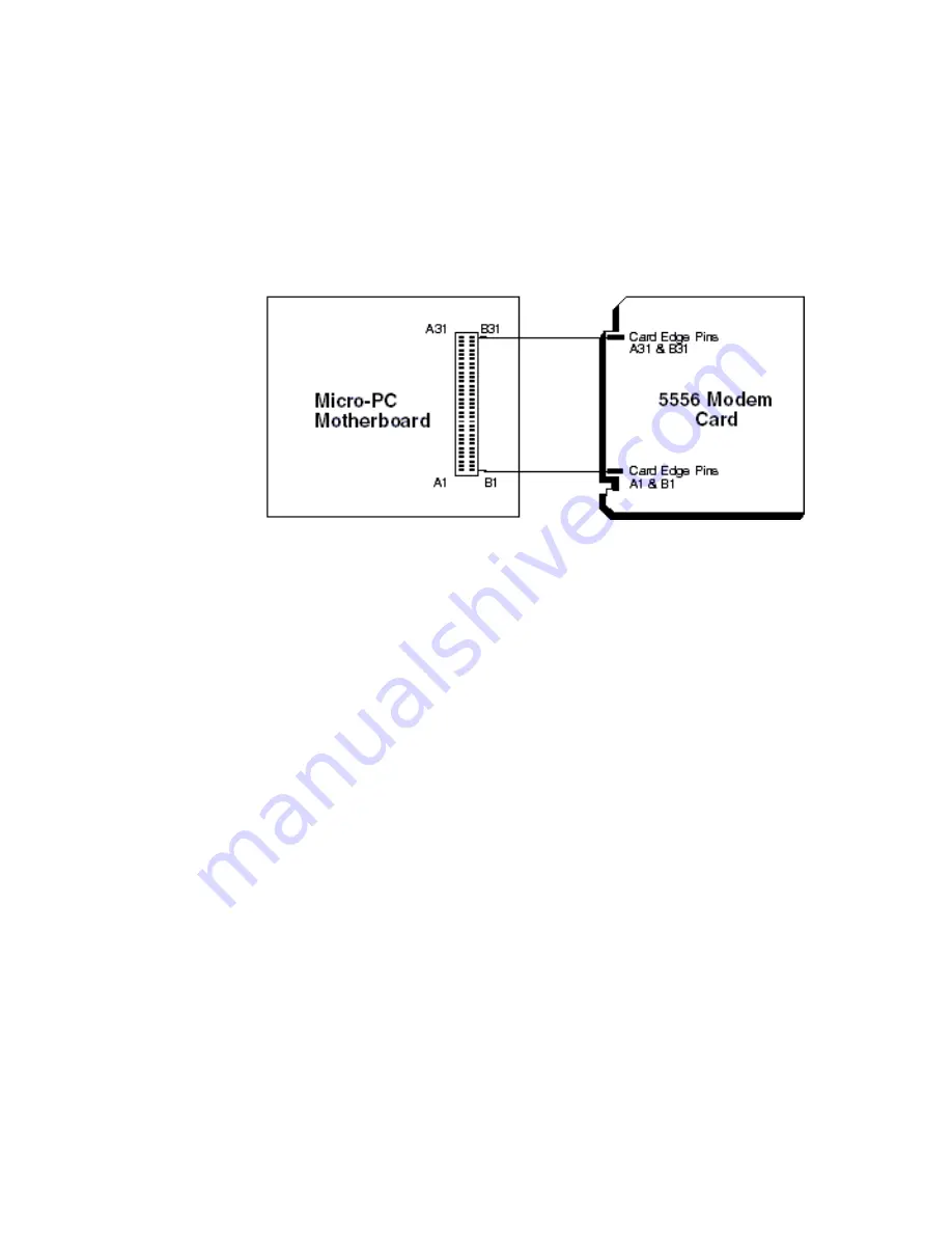
Take care to correctly position the 5556 in the card cage. The Vcc and
ground signals must match those on the backplane. Figure 2 shows
the relative position of the 5556 as it is installed in the card cage.
Figure 2
5556 Card orientation
1. Verify the interrupt and COM port selections are correct for your
application.
2. Turn the card cage power off.
3. Position the cage so that the backplane is away from you, the power
module is to the right, and the open side of the cage is closest to you.
The lettering on the backplane should be right side up (for example,
you should be able to read “A31” on the backplane), with the words
“OCTAGON SYSTEMS CORP.” running vertically along the left side
of the backplane. This position is “feet down” for a table mount cage
and “feet back” for a rear mount.
4. Slide the 5556 into the card cage. The components on the card
should face to the left. The lettering on the card (“Octagon Systems
Corp.”) should be on the top edge of the card and the gold contact
fingers toward the backplane.
5. Plug the 5556 into the backplane.
6. The amber LED will light briefly whenever the card is accessed
(input or output).
7. Unplug your telephone set’s modular cable connector from the wall
jack. Then plug it into the jack labeled PHONE on the 5556
(optional). (When using the 5556’s automatic features, there is no
need to have the telephone plugged in.)


