Operators Guide
10
Introduction
The 2575D pan and tilt head embodies a patented sinusoidal counterbalance mechanism for
true and accurate balance; stepless drag assemblies for ultra-smooth pan and tilt motions; and
an adjustable camera mounting plate.
Counterbalance
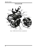
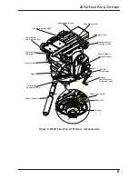
The balance mechanism is adjusted by the counterbalance crank on the lower right of the head.
The knob has a folding handle which incorporates a clutch to prevent inadvertent damage to the
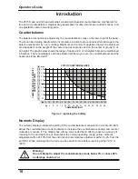
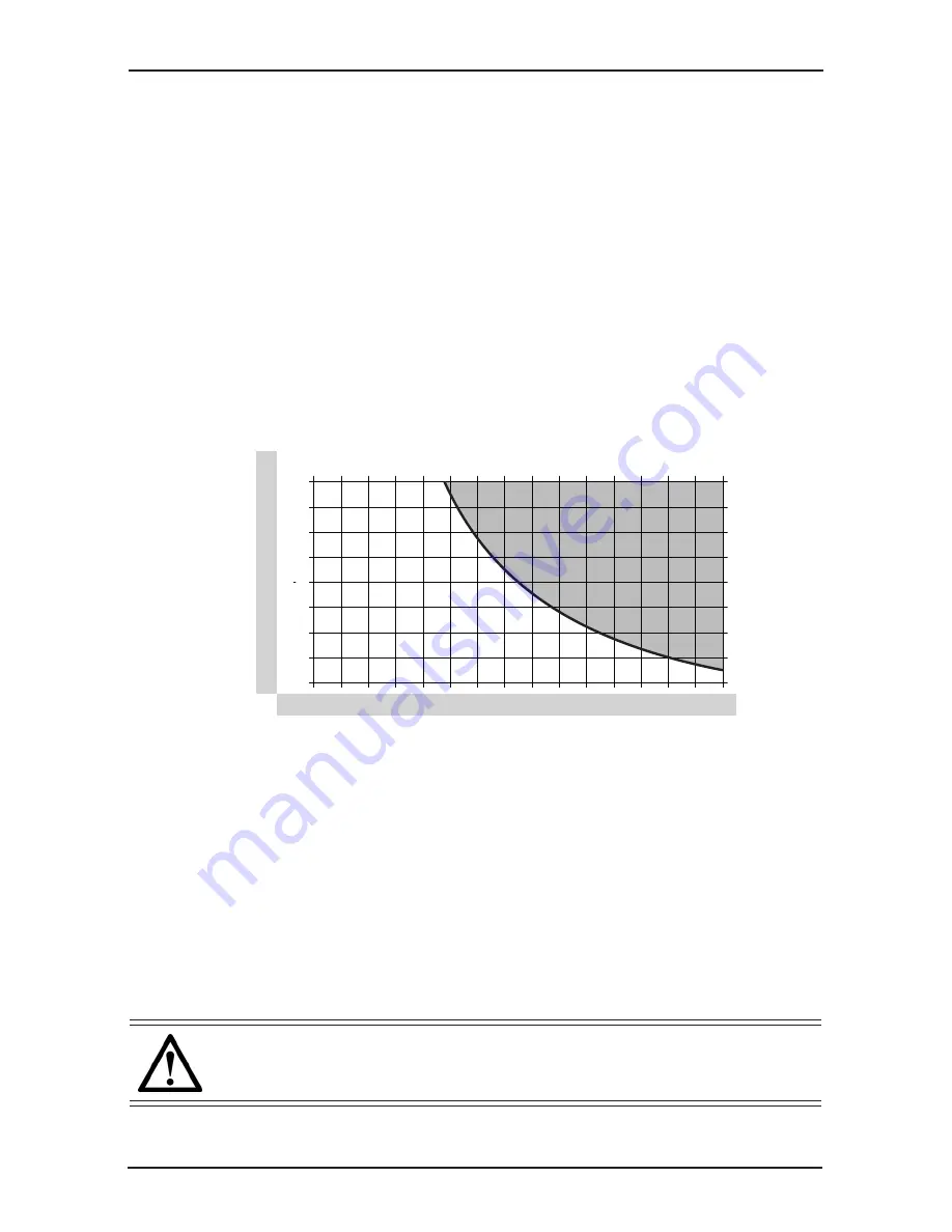
balance mechanism by over cranking. Maximum and minimum payloads that can be balanced
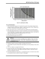
are dependent on the weight of the camera and accessories and on the center of gravity (C of
G) height. The graph below shows the range of loads and C of G heights that can be maintained
in balance. The counterbalance can be adjusted all the way to zero (no counterbalance) and the
head can still be tilted ±90º.
Numeric Display
The numeric display indicates the setting of the counterbalance mechanism on a scale of 0-99%.
Adjust the counterbalance crank clockwise to increase the counterbalance setting and counter
clockwise to reduce it. The display has a three color coded band offering advance warning of
cranking to the end limits. Green represents the normal operating range, yellow indicates
adjustment within 20-10% from the end limit and red indicates adjustment within 10-0% from the
end limit. When cranking into the red zone be careful to stop before reaching either "0%" or
"99%".
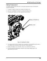
Figure 3 replacing the battery
Warning!
Do not attempt to adjust the counterbalance crank below 0% or above 99%
as damage could occur.
2
4
6
8
10
12
14
16
18
in
0
10
20
30
40
50
60
70
80
90 100 110 120 130 140 150
lbs
5
9
14
18
23
27
32
36
41
45
50
54
59
64
68
kg
51
102
152
203
254
305
356
406
457
mm
CAMERA WEIGHT
2575D COUNTERBALANCE
CAMERA
CENTER OF GRA
VITY
ABOVE PLA
TFORM


