background image


BA OCHSNER AQUA TERRA_EN_V01.1.docx


Page 61 of  72 


Summary of Contents for AQUA 54

Page 1: ...BA OCHSNER AQUA TERRA_EN_V01 1 docx Page 1 of 72 Operating Instructions Installation Instructions OCHSNER AQUA OCHSNER TERRA Brine Water Heat pump Heating Cooling Hot Water ...

Page 2: ...BA OCHSNER AQUA TERRA_EN_V01 1 docx Page 2 of 72 ...

Page 3: ...r the system installer 20 6 5 Commissioning OCHSNER 20 7 System operation 21 7 1 Menus 21 7 2 Safety functions 22 7 3 Appliance function 22 7 3 1 Heating circuit 22 7 3 2 Hot water 22 7 3 3 Anti Legionella switching 22 7 4 System operation 22 7 4 1 Running costs 22 7 4 2 Flow temperatures 22 7 5 Ventilation 22 7 6 Screed flooring drying 22 8 Maintenance 23 8 1 Service work 23 9 Trouble shooting 24...

Page 4: ...tention danger to life and limb 1 2 Safety instructions Read this manual carefully before you begin to commission adjust the heat pump Converting or altering the appliance is not allowed Work on the appliance repairs alterations may only be carried out by a specialist authorised by the manufacturer All circuit breakers in the heating sys tem are to be turned off before any work is carried out on t...

Page 5: ...AQUA and TERRA are compact appliances for indoor installation The heat pump is suitable for inside installation and NOT for outside installation The heat extraction heat source circuit takes place depending on the type via its own brine cir cuit for instance ground heat systems from flat plate collectors deep trench Künette collectors ground probes or a well as the heat source The heat pump of the...

Page 6: ... Transport damage can only be recognised if this is made known to the driver of the delivery vehicle during or immediately after unloading 3 3 Tilting dimensions of indoor unit The tilting dimension of the heat pump is 209cm Fig 2 Titling dimension of the heat pump 3 4 Select the place of instillation The heat pump TERRA can be installed in any dry and frost free room Installation must take place ...

Page 7: ...e by the electrician tak ing into account the ratings and cable lengths 4 1 Check list The stated voltage must be the same as the house circuit voltage Observe the specifica tions on the rating label The heat pump connection must have been approved by the competent utility before it is carried out The circuit breaker for the main power supply circuit 230V 400VAC is to be a fuse that switches off a...

Page 8: ...two wire cable Example eBUS SIGNAL GND Do not connect GND to the sheath 2x2x0 8 mm Table 1 Cable selection 4 3 Details of power supply The voltage supplies 400V and 230V are to be run separately according to the circuit diagram The following power supplies are necessary Fig 4 Power supply 400VAC for the compressor Utility EVU Signal contact 230V control voltage inside switching box The power suppl...

Page 9: ...re supplied with 4 0m cable lengths Should these lengths not suffice the cables can be lengthened as required Please use 2x 1 0mm flexible cable When installing the sensor cable ensure that the cables do not run parallel to alternate current 230VAC cables Outside sensor TA The outside sensor TA is to be mounted at ca 2 5 m height on the outside wall of the building north west side It is to be ensu...

Page 10: ... may only be undertaken on a fully pre pared system that is ready for commissioning A relay test can be carried out on the OTE control in order to test the appropriate outputs actuators 4 11 Safety thermostat STB in heating circuit If a non self resetting safety thermostat STB is installed on site this STB is to be installed directly in the power supply to the heating circuit pump not supplied 4 1...

Page 11: ...Power Supply 220 240VAC Control voltage Heating circuit mixing valve Open close Pin 15 16 N PE WQP and WEP pump Temperature sensor TMK Mixing circuit Pin 43 GND Temperature sensor TA outside tempera ture Pin 44 GND Temperature sensor TPM buffer middle Pin4 GND Temperature sensor TPO buffer top Pin 45 GND Temperature sensor TB hot water sensor Pin46 GND OTE control with Climate control manager Casc...

Page 12: ...be softened if this value is ex ceeded Desalinated water or rainwater must not be used as this leads to increased corrosion Please observe Unsuitable filling or topping up water gives rise to sedimentation and corro sion and can lead to system damage 5 3 Pressure maintenance system The primary pressure in the expansion vessel must be checked before filling the system This must be adjusted to the h...

Page 13: ... pump will not reach the specified catalogue rating and under certain conditions will be shut off by means of the high pressure switch ERROR re port see operation instructions OTE Integrated heating system circulation pumps are sized as buffer charge pumps technical data see annex It is recommended to install a decoupling tank separation tank buffer tank or a header tank with the heat pump A bleed...

Page 14: ...ts no liability for possible damage which may occur if the flow rate meter is either not installed incorrectly installed sized or wired up Fig 8 Flow rate measurement heating system 5 6 Setting the flow rate The nominal flow rate see is to be ensured in all types of operation hot water charging heating cooling via a separate buffer tank etc The flow rates are measured by the installed flow meter a...

Page 15: ...rational data ESC ENTER Settings Relay test 01 076 Compressor 100 01 077 HEAT PUMP 01 022 Pump heat gener 20 Heat source pum 45 ESC ENTER 20 ESC 01 022 HEAT PUMP Pump heat generator ESC 01 077 HEAT PUMP Heat source pump fan 45 HEAT PUMP ESC ENTER OCHSNER OTE MENU Sa 25 06 2016 08 10 Switched off 5 Main menue HEATING CIRCUIT 1 HEATING CIRCUIT 2 HOT WATER HEAT PUMP ESC ENTER 1 HEAT PUMP Operation mo...

Page 16: ...ng materials can lead to corro sion and clogging of the evaporator the feed pump and the pipework heat pump malfunction Adhere to the values in ATTENTION A water analysis can only be a momen tary value The values can fluctuate considerably in the course of a year The evaluation of a meaningful use can however only be carried out with the measured values Table 1 Water quality Legend the material ha...

Page 17: ...ons in the installation manual for flow rate measuring meters If the flow rate meter is either not installed or in correctly installed OCHSNER will not undertake the commissioning of the system OCHSNER accepts no liability for possi ble damage which may occur if the flow rate meter is either not installed incor rectly installed sized or wired up Fig 12 Installation of flow rate sensor heat source ...

Page 18: ...are to be checked This check is to be carried out with a representative quantity for instance 3x 1 4l The correct mix relationship is to be tested with a refractometer The filling is to be carried out in such a way as to ensure the proper bleeding of the system In order to ensure a reliable operation a temperature difference of 3K between the evaporator heat source flow and return is to be maintai...

Page 19: ...to destruction of the pump Commissioning must be carried out by Ochsner Customer Service or a service partner authorised by Ochsner The Ochsner commissioning guide lines must be adhered to Operating the system without a correct commissioning will lead to a for feiture of the guarantee and warranty rights 6 2 Check list for commissioning Adhere to the following sequence 1 Check heating system circu...

Page 20: ...ely 6 5 Commissioning OCHSNER Commissioning requests are to be made to OCHSNER Customer Service A date for commis sioning can only be made when the completed and signed commissioning form is handed in Please make appointments for fixed commission ing dates at least 2 weeks in advance To undergo the commissioning process the fol lowing work should be complete The heating and hot water systems must ...

Page 21: ...uttons at his disposal A and B as well as a lit graphic display showing the functions By pressing the right hand button A the main menu is called up in which the heating system is shown Each heat user heating circuits hot water cir cuits and each heat generator heat pump elec tric auxiliary heater furnace etc has its own menu and sub menu Return one step back ESC by pressing button B The room term...

Page 22: ...residual moisture in the building up to 50 7 4 2 Flow temperatures In order to achieve an optimum heat pump oper ation the lowest possible heating system flow temperatures and hot water temperatures are to be aimed at The maximum system temperature for the plus Series is to be limited to 60 C and all other models to max 50 C NOTE An increase of the room temperature by 1 C means a 5 7 increase in e...

Page 23: ...f the machine as well as checking the control and regulation equipment Your advantages of servic ing Correct servicing not only helps to save en ergy it also protects the environment Furthermore the correct care of the heating system is a neces sary prerequisite in order to safeguard the opera tional life of the heat pump for many years This gives the system user increased protection against malfu...

Page 24: ...ater Circulation pipework Reduce flow and use timer Hot water heat exchanger chalked up Contact heating installer clean and decal cify heat exchanger Hot water temperature not reached or no longer reached Hot water heat exchanger too small Increase heat exchanger size Heat exchanger is chalked up Decalcify heat exchanger Wrong sensor positioning Correct positioning Pipework to small Fit larger pip...

Page 25: ... Er 39 Motor protection compressor Overload heat source temperature too high Check Compressor in cooling circuit OCHSNER 8 8 Er 42 Frost protection in heating sys tem Insufficient heat distribution circulation pump defect valve closed air in the system check the buffer pump or the hydraulics Er 46 TSG sensor defect Replace sensor 9 9 Er 47 De icing malfunction Insufficient de icing energy evaporat...

Page 26: ...lfunctions He must be informed of the malfunction and can also give you valuable tips on troubleshooting Your installer knows your hydraulic system and its mode of operation The causes of the malfunction are usually to be found in the settings or the hy draulics Should the cause not be able to be found or remedied however your Ochsner Customer Service will be glad to help 9 3 Remedy small faults y...

Page 27: ...ing agents 10 Environment and recycling Please ensure that your heat pump system oper ates in an energy saving manner The Ochsner Cus tomer Service offers regular servicing for this Incorrect disposal of the refrigerant can lead to considerable environ mental damage and is a punishable offence 10 1 Disposing of the packaging The heat pump s transport packaging consists of recyclable raw materials ...

Page 28: ...he incoming inspection the warranty period shall be two years from delivery and shall neither be extended nor suspended by improvement attempts it shall also apply to partial deliveries Such defects are to be re ported in writing within 3 days from their dis covery otherwise all claims for guarantee and or damage claims and or rescission on the grounds of error will be excluded These defect do not...

Page 29: ...tics especially those in public an nouncements such as advertising and in the specifications supplied with the contractual products we only give warranty if these characteristics have been as sured in writing in the course of the procure ment Notwithstanding any other provisions in these Standard Terms and Conditions of Sale and Delivery warranty shall expire I if the Customer either himself or th...

Page 30: ...ling of the trans action shall be limited as a maximum of the value of the order which gave rise to the damage and shall always only apply in the event of our own gross negligence or of gross negligence on the part of our vicarious agents with the exception of damage to per sons for which we shall also be liable in the event of slight negligence Reimbursement of conse quential damage pure pecuniar...

Page 31: ...0 W18 65 0 97 2 121 2 kW Power consumption W10 W18 9 17 2 21 2 kW EER 3 3 W10 W18 6 2 4 7 4 7 Power consumption W10 W18 A Performance data cooling operation 1 2 Cooling capacity W10 W7 38 0 59 0 74 5 kW Exhaust heat capacity W10 W7 46 1 73 8 92 7 kW Power consumption W10 W7 8 1 14 8 18 2 kW EER 3 3 W10 W7 4 7 4 0 4 1 Power consumption W10 W7 A Compressor Construction Fully hermetic Scroll Quantity...

Page 32: ...rk 2 mm Heat carrier temperature differential 5 K Range of application 68 C Heat carrier Water Testing pressure 51 bar Refrigerant circuit Number of refrigerant circuits 1 Refrigerant R 410A Filling quantity 10 4 13 1 13 7 kg Appliance data Voltage Frequency 3 Phases 3x400 50 V Hz cos φ 0 8 0 79 0 8 Fuse protection C40 C63 C80 A Colour tiger white 29 11289 grey RAL 7016 Weight 228 284 306 kg Integ...

Page 33: ...xhaust heat capacity B25 W18 64 6 98 2 127 2 kW Power consumption B25 W18 9 2 14 9 19 3 kW EER 3 3 B25 W18 6 0 5 6 5 6 Power consumption B25 W18 18 9 25 1 34 2 A Performance data cooling operation 1 2 Cooling capacity B25 W7 34 9 54 1 61 5 kW Exhaust heat capacity B25 W7 43 2 66 9 75 7 kW Power consumption B25 W7 8 3 12 8 14 2 kW EER 3 3 B25 W7 4 2 4 2 4 3 Power consumption B25 W7 15 9 22 9 25 1 A...

Page 34: ...nnecting pipework 2 mm Heat carrier temperature differential 5 K Range of application 68 C Heat carrier Water testing pressure 51 bar Refrigerant circuit Number of refrigerant circuits 1 piece Refrigerant R 410A Filling quantity 10 4 13 0 13 3 kg Appliance data Voltage Frequency 3 Phases 400 50 V Hz cos φ 0 8 0 79 0 8 Fuse protection C40 C63 C80 A Colour tiger white 29 11289 grey RAL 7016 Weight 2...

Page 35: ...eistung kW Soletemperatur C COP Soletemperatur C Leistungsaufnahme kW 40 43 46 49 52 55 58 61 64 67 70 73 76 79 82 85 88 91 94 97 100 103 6 4 2 0 2 4 6 8 10 12 14 16 18 20 Soletemperatur C Leistungskurven TERRA 61 C 35 C 45 C 50 C 60 C 0 1 2 3 4 5 6 7 8 6 4 2 0 2 4 6 8 10 12 14 16 18 20 10 12 14 16 18 20 22 6 4 2 0 2 4 6 8 10 12 14 16 18 20 Heizleistung kW Soletemperatur C COP Soletemperatur C Lei...

Page 36: ...16 18 20 14 16 18 20 22 24 26 28 6 4 2 0 2 4 6 8 10 12 14 16 18 20 Heizleistung kW Soletemperatur C COP Soletemperatur C Leistungsaufnahme kW 40 44 48 52 56 60 64 68 72 76 8 10 12 14 16 18 20 22 24 Heizleistung kW Wassertemperatur C 35 C 45 C 50 C 60 C Leistungskurven AQUA 54 C 0 2 4 6 8 8 10 12 14 16 18 20 22 24 6 8 10 12 14 16 8 10 12 14 16 18 20 22 24 Wassertemperatur C Wassertemperatur C COP L...

Page 37: ...6 18 20 22 24 26 8 10 12 14 16 18 20 22 24 Wassertemperatur C Wassertemperatur C COP Leistungsaufnahme kW 60 70 80 90 100 110 120 130 140 8 10 12 14 16 18 20 22 24 Heizleistung kW Wassertemperatur C 35 C 45 C 50 C 60 C Leistungskurven AQUA 97 C 2 4 6 8 10 12 14 16 18 20 22 24 14 18 22 26 30 34 8 10 12 14 16 18 20 22 24 Wassertemperatur C Wassertemperatur C COP Leistungsaufnahme kW 12 7 Performance...

Page 38: ...of 72 12 9 Pump characteristics Fig 18 Pump characteristic curve Stratos Para 40 1 8 Fig 19 Pump characteristic curve Stratos Para 50 1 12 Fig 20 Pump characteristic curve Stratos Para 40 1 12 Fig 21 Pump characteristic curve Stratos Para 65 1 12 ...

Page 39: ...BA OCHSNER AQUA TERRA_EN_V01 1 docx Page 39 of 72 12 10 Pump characteristic curves well pumps Fig 22 Pump characteristic curve SP 14 4 ...

Page 40: ...BA OCHSNER AQUA TERRA_EN_V01 1 docx Page 40 of 72 12 11 Dimensions sheet SP 14 4 Fig 23 Dimensions OCHSNER TERRA ...

Page 41: ...ram heat source water Fig 24 System diagram heat source water 1 Lined conduit 2 Emptying 3 Water filter 4 Emptying 5 Water flow meter 6 Flow sensor heat source 7 Flex connecting hose heat source 8 Flex connecting hose heat use 9 Flow sensor heat use 1 6 3 2 4 5 7 8 9 9 ...

Page 42: ...mp 5 Flow sensor heat source 6 Fitting stop cocks for connecting flushing fitting 7 Flex connecting hose heat source 8 Flex connecting hose heat use 9 Flow sensor heat use All pipework fittings and hoses are to be insulated on site with non permeable insulating material The flush fitting external thread screw connections are to be sealed with Teflon tape to prevent condensation entering 1 2 3 4 5 ...

Page 43: ...61 C 922349 Stratos 50 1 12 16 267 120 922462 Stratos 65 1 12 10 7 178 45 TERRA 76 C 922462 Stratos 65 1 12 20 333 150 922462 Stratos 65 1 12 13 3 222 50 Table 5 Flow rates 12 15 Ground collector heat source brine Type Circuits á 120m for HP Type Laid surface Length of Künette Pressure loss 2 Volume 3 m m mbar Litre ESK 18 18 TERRA 40 C 1200 360 131 1440 ESK 30 30 TERRA 61 C 1980 600 169 2380 ESK ...

Page 44: ...BA OCHSNER AQUA TERRA_EN_V01 1 docx Page 44 of 72 12 16 Electrical circuit diagrams ...

Page 45: ...BA OCHSNER AQUA TERRA_EN_V01 1 docx Page 45 of 72 ...

Page 46: ...BA OCHSNER AQUA TERRA_EN_V01 1 docx Page 46 of 72 ...

Page 47: ...BA OCHSNER AQUA TERRA_EN_V01 1 docx Page 47 of 72 ...

Page 48: ...BA OCHSNER AQUA TERRA_EN_V01 1 docx Page 48 of 72 13 Disassembly assembly panel ...

Page 49: ...BA OCHSNER AQUA TERRA_EN_V01 1 docx Page 49 of 72 13 1 Dismantling the top cover 2 screws according Remove image 4 mm Allen key Cover slide a piece backwards and lift off upwards ...

Page 50: ...BA OCHSNER AQUA TERRA_EN_V01 1 docx Page 50 of 72 13 2 Disassembly of the upper cladding parts 3 screws according Remove image 4 mm Allen key 2 screws according Remove image 4 mm Allen key ...

Page 51: ...BA OCHSNER AQUA TERRA_EN_V01 1 docx Page 51 of 72 2 screws on the back remove 4 mm Allen key ...

Page 52: ... Page 52 of 72 The upper side parts left and right can be lifted The front end plate can be lifted WATCH OUT Note the wire to display 13 3 Remove the back panel parts 2 screws at the front according to the pictures removed allen key 4mm ...

Page 53: ...BA OCHSNER AQUA TERRA_EN_V01 1 docx Page 53 of 72 3 screws Left Front loud Remove image 4 mm Allen key 2 screws on the back according to the pictures removed allen key 4mm ...

Page 54: ...BA OCHSNER AQUA TERRA_EN_V01 1 docx Page 54 of 72 13 4 Dismantling of the wooden parts 16 screws according Remove image Torx T25 ...

Page 55: ...BA OCHSNER AQUA TERRA_EN_V01 1 docx Page 55 of 72 Remove the unscrewed woods Lift the machine with pallet truck ...

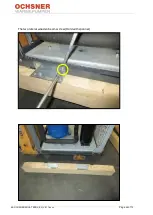
Page 56: ...BA OCHSNER AQUA TERRA_EN_V01 1 docx Page 56 of 72 The two lateral wooden beams screw Hold with spanner ...

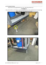
Page 57: ...age 57 of 72 13 5 Mounting the feet Mount the 4 leveling feet Ochsner Art No 916 431 with M16 nut DANGER Once the machine is on the feet may the height difference of the individual feet not be too large about 5 threads damage to the thread ...

Page 58: ...BA OCHSNER AQUA TERRA_EN_V01 1 docx Page 58 of 72 14 Declaration of Conformity ...

Page 59: ...BA OCHSNER AQUA TERRA_EN_V01 1 docx Page 59 of 72 ...

Page 60: ...BA OCHSNER AQUA TERRA_EN_V01 1 docx Page 60 of 72 ...

Page 61: ...BA OCHSNER AQUA TERRA_EN_V01 1 docx Page 61 of 72 ...

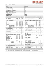
Page 62: ...t te e t p mp i t te e t p mp 0 15 i 20 15 i 20 i ent tempe t e i 10 i t te e t p mp 10 pe ti n imit tempe t e e inp t c mp e 0 e ting te pe ting imit tempe t e 8 e c n mpti n in m e t e t n cti e m e S pp ement e te m e 20 te e t tp t p 0 00 e m t t m e 20 pe ene g inp t e ect icit St n m e S 20 n c e e te m e 0 t e item p cit c nt i e i t te e t p mp m S n p e e e in 5 te i te t t te ine t te e ...

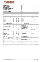
Page 63: ... t p mp 5 15 i 20 15 i 20 i ent tempe t e i 10 i t te e t p mp 10 pe ti n imit tempe t e e inp t c mp e 0 e ting te pe ting imit tempe t e 8 e c n mpti n in m e t e t n cti e m e S pp ement e te m e 20 te e t tp t p 0 00 e m t t m e 20 pe ene g inp t e ect icit St n m e S 20 n c e e te m e 0 t e item p cit c nt i e i t te e t p mp m S n p e e e in 58 te i te t t te ine t te e t p mp 1 m nn ene g c...

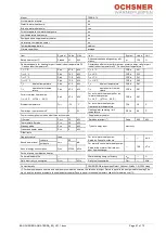
Page 64: ... t p mp 58 15 i 20 15 i 20 i ent tempe t e i 10 i t te e t p mp 10 pe ti n imit tempe t e e inp t c mp e 0 e ting te pe ting imit tempe t e 8 e c n mpti n in m e t e t n cti e m e S pp ement e te m e 20 te e t tp t p 0 00 e m t t m e 20 pe ene g inp t e ect icit St n m e S 20 n c e e te m e 0 t e item p cit c nt i e i t te e t p mp m S n p e e e in 0 te i te t t te ine t te e t p mp 1 1 m nn ene g...

Page 65: ...e 2 8 i t te e t p mp 5 i t te e t p mp i t te e t p mp 2 8 15 i 20 15 i 20 i ent tempe t e i 10 i t te e t p mp 10 pe ti n imit tempe t e e inp t c mp e 0 e ting te pe ting imit tempe t e 8 e c n mpti n in m e t e t n cti e m e S pp ement e te m e 20 te e t tp t p 0 00 e m t t m e 20 pe ene g inp t e ect icit St n m e S 20 n c e e te m e 0 t e item p cit c nt i e i t te e t p mp m S n p e e e in ...

Page 66: ...8 i t te e t p mp 55 1 i t te e t p mp i t te e t p mp 2 88 15 i 20 15 i 20 i ent tempe t e i 10 i t te e t p mp 10 pe ti n imit tempe t e e inp t c mp e 0 e ting te pe ting imit tempe t e 8 e c n mpti n in m e t e t n cti e m e S pp ement e te m e 20 te e t tp t p 0 00 e m t t m e 20 pe ene g inp t e ect icit St n m e S 20 n c e e te m e 0 t e item p cit c nt i e i t te e t p mp m S n p e e e in ...

Page 67: ...te e t p mp 2 i t te e t p mp i t te e t p mp 2 81 15 i 20 15 i 20 i ent tempe t e i 10 i t te e t p mp 10 pe ti n imit tempe t e e inp t c mp e 0 e ting te pe ting imit tempe t e 8 e c n mpti n in m e t e t n cti e m e S pp ement e te m e 20 te e t tp t p 0 00 e m t t m e 20 pe ene g inp t e ect icit St n m e S 20 n c e e te m e 0 t e item p cit c nt i e i t te e t p mp m S n p e e e in 0 te i te...

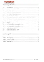
Page 68: ...YSTEM 17 FIG 13 WALL DUCTING 17 FIG 14 FLOW METER INSTALLATION IN HEAT SOURCE BRINE SYSTEM 18 FIG 15 COLLECTION SHAFT 18 FIG 16 BASIC CONTROL PANEL 21 FIG 17 OPERATION 21 FIG 18 PUMP CHARACTERISTIC CURVE STRATOS PARA 40 1 8 38 FIG 19 PUMP CHARACTERISTIC CURVE STRATOS PARA 50 1 12 38 FIG 20 PUMP CHARACTERISTIC CURVE STRATOS PARA 40 1 12 38 FIG 21 PUMP CHARACTERISTIC CURVE STRATOS PARA 65 1 12 38 FI...

Page 69: ...BA OCHSNER AQUA TERRA_EN_V01 1 docx Page 69 of 72 ...

Page 70: ...BA OCHSNER AQUA TERRA_EN_V01 1 docx Page 70 of 72 ...

Page 71: ...BA OCHSNER AQUA TERRA_EN_V01 1 docx Page 71 of 72 ...

Page 72: ...4020 Linz kontakt ochsner at www ochsner com Central works Ochsner Straße 1 A 3350 Haag Tel 43 0 5 042458 Fax 43 0 5 04245 349 kontakt ochsner at www ochsner com Partner Hotline 0820 201020 OCHSNER Ochsner Wärmepumpen GmbH Germany Riederhofstraße 27 D 60314 Frankfurt am Main kontakt ochsner de www ochsner com Partner Hotline 01805 832840 OCHSNER East PL 30 198 Kraków Zakliki z Mydlnik 16 Tel 48 0 ...

Reviews: