background image

C-Nav7050 User Guide 


Revision 0


Page 12 of 27


10/30/2020 


Control Micro 

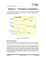
The control microprocessor is connected to both UHF modules and is capable 
of  sending  and  confirming  commands  to  change  the  current  channel.  The 
current  channel  number  is  shown  on  a  front  panel  combined  display  /  switch 
unit. The processor can also perform a scan of all programmed channels and 
select  the  one  with  the  best  signal  to  noise  ratio.  Frequency  selection  and 
scanning are thus possible without connection to an external PC.  


IALA Radio Module   

The  IALA  radio  module  can  be  configured  via  a  port  on  the  back  panel.  It  is 
normally set  to auto scan for the highest signal strength.  The output  from the 
IALA receiver is passed to the fallback switch. See Appendix C - IALA Module 
(Page 

26

) for further information.  


Auxiliary Input 

In  addition  to  the  two  UHF  and  one  IALA  sources  it  is  also  possible  to  use 
corrections from an external system via a back panel serial port. These could be 
derived from a PPP corrected receiver or be broadcast from a local RTCM base. 
There is hardware present  to support the future option of  having the auxiliary 
source  be  an  Ethernet  connection.  A  Lantronix  X-Port  module  converts  the 
Ethernet data to serial. When supported in a future release, the choice of serial 
or  Ethernet  will  be  mad  by  a  switch  on  the  back  of  the  unit.  At  this  time,  the 
switch should 

always be in the “serial” position.  


Fallback Switch   

The fallback switch examines the output of the Primary Source for data and if 
data  is  absent  for  a  period  of  time  the  fallback  switch  output  changes  to  the 
Secondary correction source. The sample period can be adjusted by an internal 
control. Should Primary source data be detected then the corrections outputs 
will switch back to the Primary source.  


Dual Outputs   

The data stream selected by the fallback switch is output by two opto-isolated 
RS- 232 ports. There are two RTCM104 outputs located on the rear panel of the 
C-Nav7050.


Summary of Contents for C-Nav7050

Page 1: ...C Nav7050 User Guide Revision 0 Revision Date November 2020 C Nav Positioning Solutions 730 E Kaliste Saloom Road Lafayette LA 70508 U S A oceaneering com cnav...

Page 2: ...User Guide Revision 0 Page 2 of 27 10 30 2020 Release Notice This is the November 2020 release of the C Nav7050 User Guide Revision History 0 11 1 2020 Initial release R Morton Revision Date Descripti...

Page 3: ...BUT NOT LIMITED TO THE IMPLIED WARRANTIES OF MERCHANTABILITY AND FITNESS FOR A PARTICULAR PURPOSE THE ENTIRE RISK AS TO THE QUALITY AND PERFORMANCE OF THE OCEANEERING INTERNATIONAL INC HARDWARE SOFTWA...

Page 4: ...ITATIONS MAY NOT APPLY TO YOU Use of this Document This User Guide is intended to be used by someone familiar with the concepts of GNSS augmentation hardware installation and rack mounted equipment in...

Page 5: ...tion 1 Overview 9 Introduction 9 Supplied Equipment 10 Optional Equipment 10 Section 2 Principles of Operation 11 UHF Radio Modules 11 Control Micro 12 IALA Radio Module 12 Auxiliary Input 12 Fallback...

Page 6: ...C Nav7050 Rear Panel 16 Figure 4 Supplied Antennas 17 Figure 5 C Nav7050 Interconnection Diagram 19 Figure 6 C Nav7050 Front Panel 20 Figure 7 Receiving Data 20 Figure 8 Not Receiving Data 21 Figure...

Page 7: ...guidance on operating the C Nav7050 Appendix A Petrobras UHF Page 22 provides the list of channels and frequencies used in Annex V Appendix B ADL RXO UHF Programming Procedures Page 23 provides instr...

Page 8: ...data This symbol means Danger You are in a situation that could cause bodily injury Before you work on any equipment be aware of the hazards involved with electrical and RF circuitry and be familiar w...

Page 9: ...lable one is from a system of UHF transmitters located on offshore platforms one from shore located IALA beacon transmitters and a third from an auxiliary source In some locations more than one UHF st...

Page 10: ...lug 3 USB Thumb Drive P N 7CNG002 0 Table 1 Supplied Equipment Optional Equipment 1 A31 Antenna GPS L1 Beacon P N CNVHEM940 2088 000 2 12 Antenna Pole P N CNVWES534610 3 UHF Antenna 460 470MHz P N CNV...

Page 11: ...robras frequencies a port on the back panel enables these frequencies to be updated The Channel frequency used by the radio is set by a combined display switch on the front panel This can be set to a...

Page 12: ...to use corrections from an external system via a back panel serial port These could be derived from a PPP corrected receiver or be broadcast from a local RTCM base There is hardware present to suppor...

Page 13: ...30 2020 Power Supply The rack is powered by an external 12V DC power source normally from a dual redundant power supply As a default during assembly the input source provides power to all the modules...

Page 14: ...quency Stability 1 PPM Channel Spacing 12 5 25 kHz user selectable Sensitivity 110 dBm BER 1 x 10 5 Adjacent Channel Selectivity 55 dB Type Certification Certified for operation in the U S Europe Aust...

Page 15: ...et 8 Hz 27 ppm Adjacent Channel Rejection 61 dB 1 dB frequency center 400 Hz Antenna Input Impedance 50 Ohms Decoding RTCM 6 8 Frequency Selection Manual or offset Serial Ports 2 full duplex Interface...

Page 16: ...with the C Nav7050 4 Slide the C Nav7050 onto the rails ensuring that the C Nav7050 is secured onto the outer rails 5 Connect the IALA antenna cable to the TNC receptacle labeled IALA if this option i...

Page 17: ...n installed it will come with the antennas mentioned in Figure 4 Page 17 Figure 4 Supplied Antennas Determining Proper Antenna Placement UHF and Beacon antennas may be placed along handrails with a cl...

Page 18: ...nd radius of 1 installation and 4 repeated 4 Ensure there is sufficient space at the cable entry point to the bulkhead as to not damage the connector during installation 5 Measure the length of the ca...

Page 19: ...fication purposes 9 Connect the coaxial cable to the sensor Ensure that any slack in the cable is neatly stowed and that the minimum bend radius is not exceed during this process Interconnection Diagr...

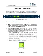
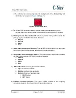
Page 20: ...he appropriate channel for each of the two UHF receivers When the proper UHF Receiver is selected the user can either advance to a known channel or scan to a receiving channel Channel selection is per...

Page 21: ...RTCM corrections between a UHF 1 b UHF 2 c IALA d Aux 5 Same Source Selection Warning This red LED is illuminated if the user sets both the primary and secondary switches to the same position 6 Second...

Page 22: ...endix shows the Petrobras UHF channels used for Annex V Channel Frequency MHz Channel Frequency MHz Channel Frequency MHz Channel Frequency MHz 00 459 2500 03 459 4250 06 469 2750 09 469 4500 01 459 2...

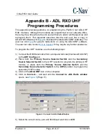
Page 23: ...user can also contact C Nav Support if they require any further assistance To program the UHF modules use the following steps 1 Connect the DB9 Serial cable from a computer terminal that has ADLCONF t...

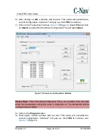
Page 24: ...on Import to upload the Petrobras Configuration File and press Open Figure 10 Frequency Configuration Window Please Note If the Petrobras Configuration File is not available then manually enter the fr...

Page 25: ...7 10 30 2020 Figure 11 Action Overwrite Window 10 Figure 12 Page 25 shows the configuration being read Figure 12 Reading Configuration Window 11 Click OK on the window that states Radio s configuratio...

Page 26: ...necessary It is not recommended to make any changes to the IALA module unless instructed by a C Nav Technician for testing purposes The receiver has two ports P0 is the RTCM104 output port and has bee...

Page 27: ...the receiver by using commands on the computer and refer to the GNSS diagrams if applicable to see which port is currently used for IALA Click here to download the latest version Note file size is ap...

Reviews: