


17
Installing the Printer
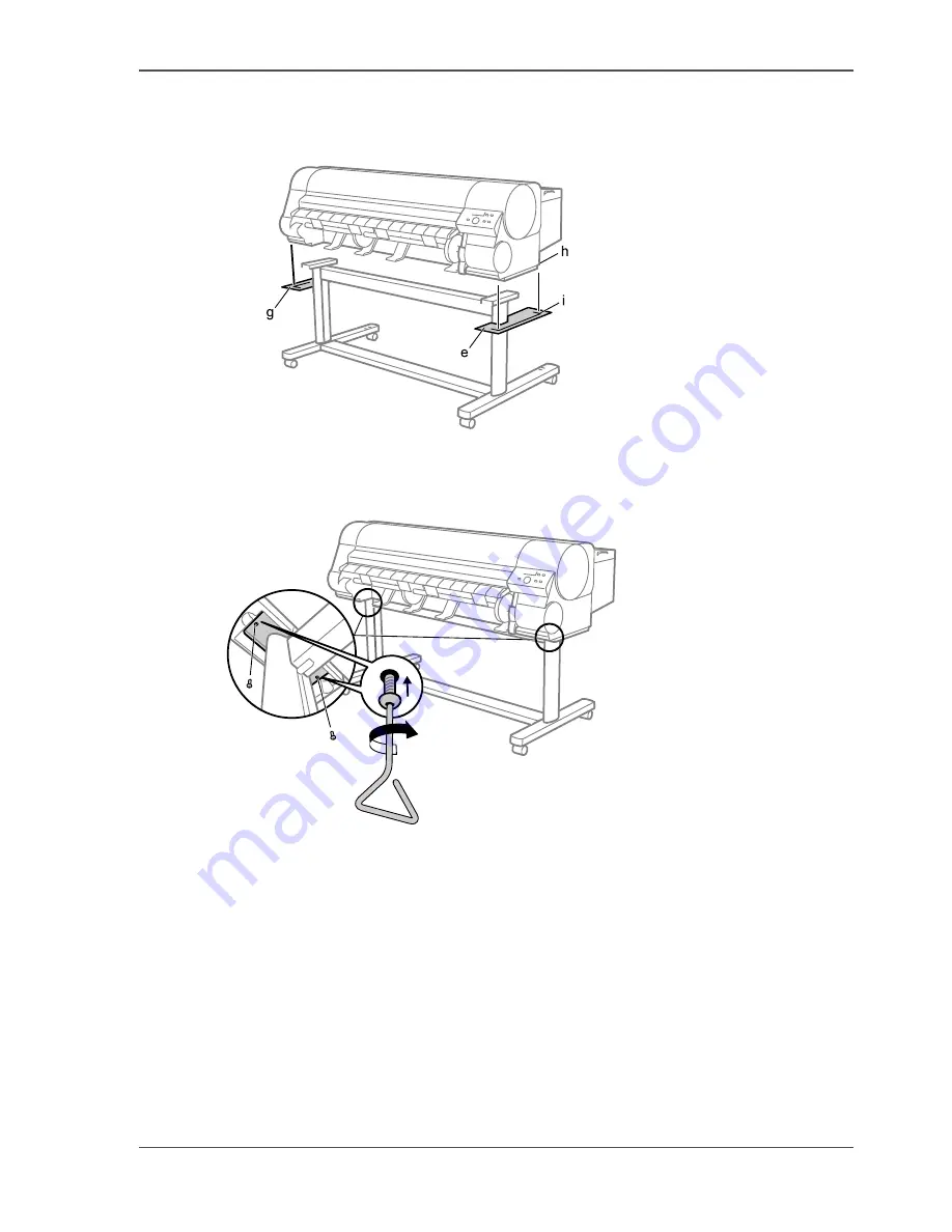
3.
Have 4 people grasp the handholds in the base of the printer body, then align the side
of the printer body (h) with the line on the Stand Extension Board (i) and put the
printer on the stand.
[45]
4.
Remove Stand Extension Board (e) and (g) from the Stand Legs.
5.
Securely affix the printer body to the stand using 2 hex screws on each side starting
from the bottom of the stand backing plate.
[46]
Summary of Contents for CS2044
Page 1: ...Oc CS2044 Oc User manual Quick Start Guide...
Page 4: ...4 Contents...


