background image


OMC-183-ML Manual


Page 13 

3.  Commissioning the OMC-183-ML 

There are two output options, both use one way RS-422 serial communication. One contains the 
NMEA data protocol format. The other one got the old OMC-2900 format for backwards 
compatibility purposes. To execute analog input calibration and other configuration settings, there 
is also a bi-directional RS-232 menu available. 
To read the sensors, each unit contains four 0-5 Voltage inputs and three 0-24mA current inputs. 
All these analog inputs have already been configured during the manufacturing process.  


3.1. 

Connecting your PC / laptop to the OMC-183-ML 

Since most computers don

’t have a comport any more, an additional Serial to USB adapter is 

needed. Install a terminal program like HyperTerminal, OMC-Terminal, , etc. and use 
the following settings for the different COM ports. 


NO flow control! 


3.2. 

Device status  

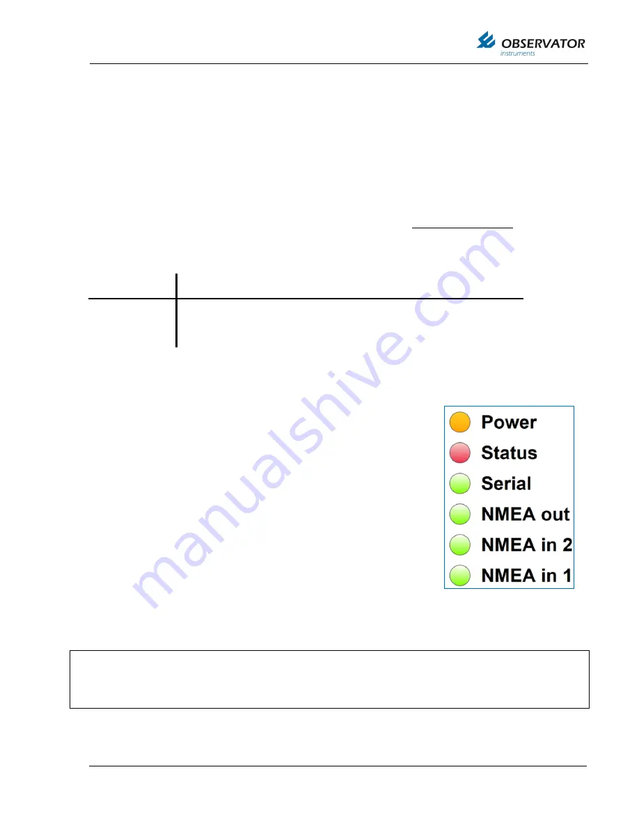
There are six LED’s on the bottom right corner of the printed circuit board, 
they indicate the status of the device. After power-up the orange LED 
indicates that the microcontroller is powered. The second LED is red and 
indicates a bus overflow, when this LED blinks there is too much data 
input to send all incoming messages as output. In this case the device 
has to ignore some input messages and information might not be sent as 
output and information might get lost. 
 
The other four green LED’s indicate the status of the 

Serial

NMEA out

NMEA in 2

NMEA in 1

 inputs. When valid messages are received these 

LED’s blink. All NMEA messages have to be compliant in order to let de 
LED blink. For the serial LED a blink means that a valid      RS-485, RS-
232 or other sensor message is received. For each serial sensor a 
software driver is included in the device. In order to connect jet unknown 
sensors an additional driver and new firmware is needed. 


Connector pins 

 
Interface 

Default data settings 

Baud rate, Data bits, Parity, stop bit 


NMEA OUT 

1-4 

RS-422 

4800 (or 9600), 8, N, 1  

OMC-2900 OUT  6-7 

RS-422 

4800, 8, N, 1 


Interface 

17-20 

RS-232 

115200 (or 4800/9600), 8, N, 1 

If you e

xperience difficulties connecting with the device; Check if the LED’s are blinking, Check the 

wiring of the Tx/Rx or A/B wires; Check the data settings of your COM port. 
 
Note: The RJ-45 / Ethernet option is not active on the OMC-183-

ML, theses LED’s are switched off. 

Summary of Contents for OMC-183-ML

Page 1: ...OMC 183 ML Signal Conditioning Unit Installation technical user manual Version 1 05 2019 Author Observator Instruments...

Page 2: ...installation technical user manual 0 2 26 09 2016 Review version 1 01 25 10 2016 First release 1 02 24 9 2018 Correction in connection OMC 938 display page 12 1 03 15 11 2018 Correction baud rate OMC...

Page 3: ...OIC 406 TEMPERATURE HUMIDITY SENSOR 10 2 7 OMC 406 TEMPERATURE HUMIDITY SENSOR 10 2 8 OMC 506 SINGLE BAROMETRIC PRESSURE SENSOR 4 20MA 11 2 9 OMC 9501 BAROMETRIC PRESSURE SENSOR S 0 2 5V 0 5V 11 2 10...

Page 4: ...OMC 183 ML Manual Page 4 Page intentionally left blank...

Page 5: ...183 has been revised and all types of OMC 183 are included into one hardware design The following inputs and outputs are available Inputs name Functionality 0 5Vdc IN 1 Voltage in no 1 0 5Vdc IN 2 Vol...

Page 6: ...OMC 138 139 OMC 938 939 OMC data Online OMC DOL HMS Typical configuration with OMC 160 wind sensor OMC 406 temperature humidity sensor dual barometric pressure sensor The OMC 506 must be vented outsid...

Page 7: ...HIELD 21 RS485_422_IN_A 6 NMEA_RETURN_A 22 RS485_422_IN_B 7 NMEA_RETURN_B 23 GND 8 SHIELD 24 SUPPLY 9 GND SUP 25 0 5VDC_IN_1 10 SUPPLY 26 GND 11 NMEA1_IN_A 27 SUPPLY 12 NMEA1_IN_B 28 0 24mA_IN_1 13 GN...

Page 8: ...out Recommended cable shielded 2x2x0 75mm2 twisted pair OMC 160 NO Jumper on 13 14 The optional heater will require a separate power supply Refer to OMC 160 manual 2 3 OMC 116 Wind sensors NMEA The Ul...

Page 9: ...box is part of the optional bracket OMC 122 M 2 5 OMC 150 158 EEx Wind sensor The old OMC 158 is not compatible met the OMC 183 ML however the new OMC 158 2 contains RS 422 NMEA output signal and is c...

Page 10: ...analog outputs These signals can be connected to OMC 183 ML by using two of the analog current input ports for example current inputs 2 3 Recommended cable shielded 2x2x0 75mm2 twisted pair OMC 183 ML...

Page 11: ...same housing as the OMC 183 ML Connections of sensor wires are identical 2 9 OMC 9501 Barometric pressure sensor s 0 2 5V 0 5V OMC 183 ML OMC 9501 Sensor 1 2 V_IN 66 69 VOUT V out GND 67 70 GND Power...

Page 12: ...75mm2 twisted pair The OMC 938 is usually connected to the RS422 output of the OMC 183 ML With the OMC 183 ML it s no longer optional to use current loop output Reconfigure the OMC 938 9 to RS422 if...

Page 13: ...ontroller is powered The second LED is red and indicates a bus overflow when this LED blinks there is too much data input to send all incoming messages as output In this case the device has to ignore...

Page 14: ...metric pressure must be measured with a minimum of 2 sensors placed at the same location These Dual barometric sensors have been implemented in the OMC 183 ML according to the CAP 437 One important im...

Page 15: ...ro sensor range 800 1100 mB 2 0 20 mA INPUT 3 pin 63 4 20 mA Baro sensor range 800 1100 mB 3 0 5 V INPUT 1 pin 25 not assigned 4 0 5 V INPUT 2 pin 48 not assigned 5 0 5 V INPUT 3 pin 66 not assigned 6...

Page 16: ...cated on the extension board therefore they need calibration after the assembly line Please make sure calibrated equipment is used to present the right current or voltage If the presented values are w...

Page 17: ...55 Current Input 3 pin 63 0 mA value 421 24 mA value 63132 Voltage Input 3 pin 66 0 Volt value 536 5 Volt value 64310 Voltage Input 4 pin 69 0 Volt value 536 5 Volt value 64309 Always use the Q comman...

Page 18: ...OMC 183 ML Manual Page 18 5 EU DECLARATION OF CONFORMITY...

Reviews: