background image

Instrucciones de montaje de abrazadera de puesta a tierra con fleje para zonas Ex 

ES | 37

Información del producto 

3.2 

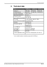
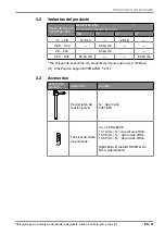
Variantes del producto

Rango de sujeción 

(mm)/Ø de tubo

Material de tubo/ 

Corriente de impulso tipo rayo*
V2A

FT

Cu

ST

6 ... <28

12,5 kA

25 kA

26,9 ... 300

50 kA (N)

28 ... 300

50 kA (N)

300 ... 500

50 kA (N)

50 kA (N)

* Sin chispas de encendido con corriente de impulso tipo rayo 

(

10/350 µs).

(N) - Clasificación según IEC/EN 62561-1:2017.

3.3 

Accesorios

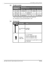
Gráfico del 

producto

Accesorios

 Detalles

Herramienta de 

tensión previa

N.° de artículo 


5057 690

Terminal de cable 

de prensado

Cu-Vz DIN 46235,

10-16 mm², N.° de artículo 01924,

10-35 mm², N.° de artículo 01931,

10-50 mm², N.° de artículo 01934, 

fabricante: Druseidt GmbH & Co. 

KG o equivalente

Summary of Contents for 5057 630

Page 1: ...helle für Ex Bereiche Montageanleitung EN Strip earthing clamp for Ex areas Mounting instructions ES Abrazadera de puesta a tierra con fleje para zonas Ex Instrucciones de montaje RU Заземляющая ленточная скоба для взрывоопасных зон Инструкция по монтажу ...

Page 2: ...al así como la reproducción impresa o electrónica Копирование воспроизведение а также частичное копирование и воспроизведение любыми фотомеханическими и электронными способами запрещено EX BES Banderdungsschelle für Ex Bereiche Montageanleitung EX BES strip earthing clamp for Ex areas Mounting instructions EX BES Abrazadera de puesta a tierra con fleje para zonas Ex Instrucciones de montaje EX BES...

Page 3: ... 3 EX BES DE 5 EN 19 ES 33 RU 47 ...

Page 4: ...OBO Bettermann 4 DE ...

Page 5: ... Zugrunde liegende Normen und Richtlinien 5 2 Allgemeine Sicherheitshinweise 5 3 Informationen zum Produkt 6 3 1 Produktübersicht 6 3 2 Produktvarianten 7 3 3 Zubehör 7 4 Montage 8 4 1 Banderdungsschelle positionieren 8 4 2 Spannband spannen 10 4 3 Druckschrauben anziehen 11 4 4 Potentialanschluss herstellen 12 4 4 1 Anschlussmöglichkeiten 12 4 4 2 Potentialanschluss montieren 13 5 Wartung 14 6 De...

Page 6: ...cht zugäng lich aufbewahrt werden um bei Informationsbedarf zur Verfügung zu stehen Für Schäden die entstehen weil diese Anleitung nicht beachtet wur de übernehmen wir keine Gewährleistung Abbildungen haben lediglich Beispielcharakter Verarbeitungsergeb nisse können optisch abweichen 1 3 Typen von Sicherheitshinweisen WARNUNG Art der Gefährdung Bezeichnet eine möglicherweise gefährliche Situation ...

Page 7: ... EX BES Bander dungsschellen für einen anderen Zweck eingesetzt werden erlöschen alle Haftungs Gewährleistungs und Ersatzansprüche 1 5 Zugrunde liegende Normen und Richtlinien Explosionsgruppe nach ATEX Produktrichtlinie IIC Geprüft nach VDE 0185 561 1 IEC EN 62561 1 Blitzschutzsystem bauteile LPSC Teil 1 Anforderungen an Verbindungsbauteile Klassifikation nach VDE 0185 561 1 IEC EN 62561 1 lösbar...

Page 8: ...ht 1 2 3 4 5 8 9 10 12 6 7 11 Abb 1 Produktübersicht 1 Kunststoffhaube PA 8 Potentialanschlussstelle M10 2 Druckschraube M6 1 9 Beschriftungsfeld 3 Druckwanne 10 Isolierende Flügel 4 Spannschraube M6 11 Leistungsschild 5 Spannband V2A 12 Kontaktkörper ZnAl 6 Schellenkörper 7 Druckschraube M6 2 ...

Page 9: ... 5 kA 25 kA 26 9 300 50 kA N 28 300 50 kA N 300 500 50 kA N 50 kA N Zündfunkenfreiheit bei Blitzstoßstrom 10 350 µs N Klassifikation nach IEC EN 62561 1 2017 3 3 Zubehör Produktgrafik Zubehör Details Vorspannwerkzeug Art Nr 5057 690 Presskabelschuh Cu Vz DIN 46235 10 16 mm Art Nr 01924 10 35 mm Art Nr 01931 10 50 mm Art Nr 01934 Lieferant Druseidt GmbH Co KG oder gleichwertig ...

Page 10: ...ge den Kontaktkörper kontrollieren isolierende Flügel kontrollieren und Verschmutzungen reinigen 4 1 Banderdungsschelle positionieren 1 Anstrich Beschichtung und Korrosionsschutz an der Kontaktstelle des Rohrs entfernen Ausnahme feuerverzinkte Schutzschicht 2 Spannschraube 4 lösen um das Spannband 5 zu lockern Schlüsselweite 10 mm Abb 2 Banderdungsschelle positionieren 3 Banderdungsschelle mit dem...

Page 11: ...nband 5 um das Rohr legen und unterhalb der Druckwanne 3 durch den Schellenkörper 6 führen WARNUNG Explosionsgefahr Eine Berührung von Spannband und Kontaktkörper kann im Falle eines Blitzeinschlags zur Funkenbildung führen Spannband parallel zu den isolierenden Flügeln montieren und span nen sodass sich Spannband und Kontaktkörper nicht berühren 5 Spannband 5 handfest spannen 6 Spannschraube 4 ha...

Page 12: ... spannen 1 Ende des Spannbandes 5 mit einer Blechschere auf ca 60 mm kürzen 60 mm Abb 4 Spannband kürzen 2 Spannschraube 4 lösen Abb 5 Spannband vorspannen 3 Vorspannwerkzeug auf das Spannband 5 setzen und drehen um das Spannband 5 vorzuspannen ...

Page 13: ...nen und Spannschraube 4 mit 8 Nm nachziehen 4 3 Druckschrauben anziehen 10 mm Abb 6 Druckschrauben anziehen 1 Druckschrauben 2 7 mit 2 Nm abwechselnd anziehen sodass sich die Kunststoffhaube 1 parallel zum Rohr anhebt Schlüsselweite 10 mm Hinweis Die gelbe reaktive Schraubensicherung braucht ca 6 Stunden um vollständig auszuhärten Die Schrauben der Banderdungsschelle nach der Montage nicht wieder ...

Page 14: ...4 1 Anschlussmöglichkeiten Anschlussleiter Werkstoff Querschnitt mm2 Ø mm mehrdrähtige oder feindrähtige Leiter Kupfer 16 25 35 50 Rundleiter Aluminium Kupfer Stahl verzinkt Edelstahl V2A V4A 50 8 78 10 Anschluss mittels Presskabelschuh siehe 3 3 Zubehör auf Seite 9 ...

Page 15: ...Werkzeug fachgerecht verpressen WARNUNG Explosionsgefahr Öl Staub Verschmutzungen und Kratzer auf den Kontaktflächen kön nen im Falle eines Blitzeinschlags zur Funkenbildung führen Vor der Montage die Kontaktlächen kontrollieren und Verschmutzungen reinigen 17 mm 20 Nm Abb 7 Potentialanschluss herstellen 2 Presskabelschuh an der Pontentialanschlussstelle 8 montieren Anzugsdrehmoment 20 Nm Schlüsse...

Page 16: ...r hinaus können in nationalen Gesetzen und Normen weitere Wartungshinweise enthalten sein die ebenfalls zu beachten sind 6 Demontage 1 Banderdungsschelle vom Rohr entfernen 2 Korrosionsschutz an der Kontaktfläche des Rohrs erneuern Hinweis Die Banderdungsschelle nach der Demontage nicht erneut verwenden 7 Entsorgung Metallteile wie Altmetall Kunststoffteile wie Hausmüll Örtliche Müllentsorgungsvor...

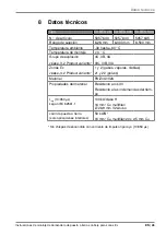
Page 17: ...etemperatur 0 C Explosionsgruppe s 3 2 Produktvarianten IIC IIB IIA IIIC IIIB IIIA Ex Zonen s 3 2 Produktvarianten 1 und 2 Gase Dämpfe Nebel 21 und 22 Stäube Material PA ZnAl V2A Materialeigenschaften UV stabilisiert witterungsbeständig Iimp 10 350 µs nach IEC 62561 1 100 kA class H 16 mm Cu mehradrig Ø 26 9 mm V2A Rohr Erdungsschiene nur Innenanwendungen 50 kA N 16 mm Cu mehradrig 20 x 2 5 mm Cu ...

Page 18: ... 2019 OBO Bettermann Holding GmbH Co KG Reprinting even of extracts as well as photographic or electronic reproduction are prohibited EX BES strip earthing clamp for Ex areas Mounting instructions ...

Page 19: ...ds and directives 21 2 General safety information 21 3 Information on the product 22 3 1 Product overview 22 3 2 Product variants 23 3 3 Accessories 23 4 Mounting 24 4 1 Positioning the strip earthing clamp 24 4 2 Tensioning the tightening strap 26 4 3 Tightening the pressure screws 27 4 4 Creating the potential connection 28 4 4 1 Connection options 28 4 4 2 Mounting the potential connection 29 5...

Page 20: ... compilation 06 2019 All the documents supplied with the product must be stored in an easily accessible location so as to be available when information is required We will not accept any warranty claims for damage caused through non observance of these instructions Any images are intended merely as examples Processing results may look different 1 3 Types of safety information WARNING Type of risk ...

Page 21: ... for another purpose any liability warranty or damage claims shall be rendered null and void 1 5 Basic standards and directives Explosion group according to the ATEX product guideline IIC Tested according to VDE 0185 561 1 IEC EN 62561 1 Lightning protection system components LPSC Part 1 Requirements for connection components Classification according to VDE 0185 561 1 IEC EN 62561 1 Re leasable co...

Page 22: ... 1 2 3 4 5 8 9 10 12 6 7 11 Fig 1 Product overview 1 Plastic hood PA 8 Potential connection point M10 2 Pressure screw M6 1 9 Labelling panel 3 Pressure trough 10 Insulating wings 4 Tensioning screw M6 11 Rating plate 5 Tightening strap V2A 12 Contact body ZnAl 6 Clamp element 7 Pressure screw M6 2 ...

Page 23: ...00 50 kA N 28 300 50 kA N 300 500 50 kA N 50 kA N Lack of ignition sparks on lightning surge current 10 350 µs N Classification according toIEC EN 62561 1 2017 3 3 Accessories Product graphic Accessories Details Pre tensioning tool Article No 5057 690 Crimping cable shoe Cu Vz DIN 46235 10 16 mm Article No 01924 10 35 mm Article No 01931 10 50 mm Article No 01934 manufacturer Druseidt GmbH Co KG o...

Page 24: ...he contact body and insulating wings and clean off any soiling 4 1 Positioning the strip earthing clamp 1 Remove the coating and corrosion protection at the contact point of the pipe exception hot galvanised protective layer 2 Slacken the tensioning screw 4 to loosen the tightening strap 5 WAF 10 mm Fig 2 Positioning the strip earthing clamp 3 Place the strip earthing clamp and the contact body 12...

Page 25: ... the pipe and run it beneath the pressure trough 3 through the clamp element 6 WARNING Risk of explosion If there is a lightning strike contact between the tightening strap and the contact body can lead to spark formation Mount the tightening strap in parallel to the insulating wings and tension it so that the tightening strap and contact body do not touch 5 Tension the tightening strap 5 so that ...

Page 26: ...ers shorten the end of the tightening strap 5 to approx 60 mm 60 mm Fig 4 Shortening the tightening strap 2 Slacken the clamping screw 4 Fig 5 Pre tensioning the tightening strap 3 Place the pre tensioning tool on the tightening strap 5 and turn it to pre tension the tightening strap 5 ...

Page 27: ...tool and tighten the clamping screw 4 with 8 Nm 4 3 Tightening the pressure screws 10 mm Fig 6 Tightening the pressure screws 1 Alternately tighten the pressure screws 2 7 with 2 Nm so that the plastic hood 1 lifts off in parallel to the pipe WAF 10 mm Note The yellow reactive screw lock requires approx 6 hours to harden fully Do not slacken the screws of the strip earthing clamp again after mount...

Page 28: ...onnection options Connection conductor Material Intersection mm2 Ø mm Multi wire or fine wire conductors Copper 16 25 35 50 Round conductor Aluminium Copper Steel galvan ised Stainless steel V2A V4A 50 8 7 10 Connection using crimping cable shoe see 3 3 Accessories on page 23 ...

Page 29: ...s details using the tool specified by the manufacturer WARNING Risk of explosion If there is a lightning strike oil dust soiling and scratches on the con tact surfaces can form sparks Before mounting check the contact surfaces and clean off any soiling 17 mm 20 Nm Fig 7 Creating the potential connection 2 Mount the crimping cable shoe at the potential connection point 8 Tightening torque 20 Nm WAF...

Page 30: ... In addition national laws and standards may contain additional main tenance instructions which must also be observed 6 Dismantling 1 Remove the strip earthing clamp from the pipe 2 Replace the corrosion protection at the contact surface of the pipe Note Do not reuse the strip earthing clamp after dismantling 7 Disposal Metallic parts as scrap metal Plastic parts as domestic waste Comply with the ...

Page 31: ...ture 0 C Explosion group see 3 2 Product variants IIC IIB IIA IIIC IIIB IIIA Ex zones see 3 2 Product variants 1 and 2 gases vapours mists 21 and 22 dusts Material PA ZnAl V2A Material properties UV stabilised Weatherproof Iimp 10 350 µs according to IEC 62561 1 100 kA class H 16 mm Cu multi wire Ø 26 9 mm V2A pipe earthing rail indoor applications only 50 kA N 16 mm Cu multi wire 20 x 2 5 mm Cu L...

Page 32: ...BO Bettermann Holding GmbH Co KG Está prohibida la impresión total o parcial así como la reproducción impresa o electrónica EX BES Abrazadera de puesta a tierra con fleje para zonas Ex Instrucciones de montaje ...

Page 33: ...s generales de seguridad 35 3 Información del producto 36 3 1 Sinopsis de los productos 36 3 2 Variantes del producto 37 3 3 Accesorios 37 4 Montaje 38 4 1 Posicionar la abrazadera de puesta a tierra con fleje 38 4 2 Tensión de la cinta de sujeción 40 4 3 Fijación de los tornillos a presión 41 4 4 Establecimiento de conexión equipotencial 42 4 4 1 Posibilidades de conexión 42 4 4 2 Montaje de cone...

Page 34: ... Todos los documentos suministrados con el producto deben guardar se en un lugar de fácil acceso para que estén disponibles cuando se necesite información No asumimos garantía alguna por daños resultantes del no segui miento de este manual Las imágenes solo sirven de ejemplo El aspecto de los resultados de procesamiento puede diferir 1 3 Tipos de indicaciones de seguridad ADVERTENCIA Tipo de pelig...

Page 35: ...on fleje EX BES con otro fin se extinguen todos los derechos de responsabilidad garantía y sustitución 1 5 Normativa y directivas básicas Grupo de explosión según directiva sobre productos ATEX IIC Probado según VDE 0185 561 1 IEC EN 62561 1 componentes de los sistemas de protección contra rayos LPSC Parte 1 Requisitos para los componentes de conexión Clasificación según VDE 0185 561 1 IEC EN 6256...

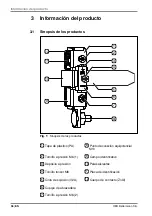
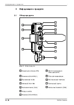
Page 36: ... 11 Fig 1 Sinopsis de los productos 1 Tapa de plástico PA 8 Punto de conexión equipotencial M10 2 Tornillo a presión M6 1 9 Campo identificativo 3 Depósito a presión 10 Palas aislantes 4 Tornillo tensor M6 11 Placa de identificación 5 Cinta de sujeción V2A 12 Cuerpo de contacto ZnAl 6 Cuerpo de abrazadera 7 Tornillo a presión M6 2 ...

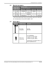
Page 37: ...6 9 300 50 kA N 28 300 50 kA N 300 500 50 kA N 50 kA N Sin chispas de encendido con corriente de impulso tipo rayo 10 350 µs N Clasificación según IEC EN 62561 1 2017 3 3 Accesorios Gráfico del producto Accesorios Detalles Herramienta de tensión previa N de artículo 5057 690 Terminal de cable de prensado Cu Vz DIN 46235 10 16 mm N de artículo 01924 10 35 mm N de artículo 01931 10 50 mm N de artícu...

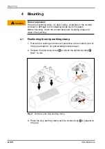
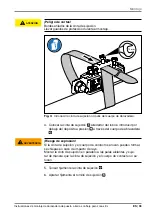
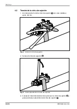
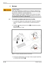
Page 38: ...trolar las palas aislantes y limpiar los contaminantes 4 1 Posicionar la abrazadera de puesta a tierra con fleje 1 Eliminar pintura revestimiento y protección contra corrosión del punto de contacto del tubo excepción capa protectora galvanizada en caliente 2 Soltar el tornillo de sujeción 4 para aflojar la cinta de sujeción 5 Ancho de llave 10 mm Fig 2 Posicionar la abrazadera de puesta a tierra c...

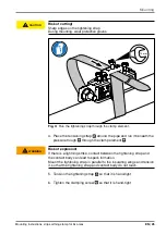
Page 39: ... la cinta de sujeción 5 alrededor del tubo e introducir por debajo del depósito a presión 3 a través del cuerpo de abrazadera 6 ADVERTENCIA Riesgo de explosión Si la cinta de sujeción y el cuerpo de contacto se rozan pueden formar se chispas en caso de impacto de rayo Montar la cinta de sujeción en paralelo a las palas aislantes y suje tar de manera que la cinta de sujeción y el cuerpo de contacto...

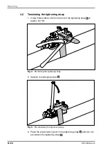
Page 40: ...cinta de sujeción 5 con unas cizallas a aprox 60 mm 60 mm Fig 4 Acortar la cinta de sujeción 2 Soltar el tornillo de sujeción 4 Fig 5 Tensar previamente la cinta de sujeción 3 Colocar la herramienta de tensión previa en la cinta de sujeción 5 y girar para tensar previamente la cinta de sujeción 5 ...

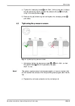
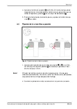
Page 41: ...r el tornillo de suje ción 4 con 8 Nm 4 3 Fijación de los tornillos a presión 10 mm Fig 6 Fijación de los tornillos a presión 1 Apretar alternativamente los tornillos de presión 2 7 con 2 Nm de forma que la tapa de plástico 1 se levante en paralelo al tubo Ancho de llave 10 mm Nota El fijador de tornillos reactivo amarillo necesita aprox 6 horas para endurecerse totalmente No volver a soltar los t...

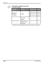
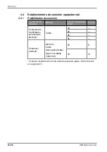
Page 42: ...nexión Conductor de conexión Material Sección transversal mm2 Ø mm Conductores multifilares o conductores flexibles Cobre 16 25 35 50 Conductor redondo Aluminio Cobre Acero galvanizado Acero inoxidable V2A V4A 50 8 78 10 Conexión mediante terminal de cable de prensado véase 3 3 Accesorios en la página 37 ...

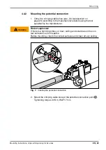
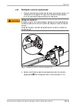
Page 43: ...amienta especificada por el fabricante ADVERTENCIA Riesgo de explosión El aceite el polvo los contaminantes y arañazos en las superficies de contacto pueden provocar la formación de chispas en caso de impacto de rayo Antes del montaje controlar las superficies de contacto y limpiar los contaminantes 17 mm 20 Nm Fig 7 Establecimiento de conexión equipotencial 2 Montar el terminal de cable de prensa...

Page 44: ... pueden incluirse otras notas de mantenimiento que deben respetarse 6 Desmontaje 1 Retirar la abrazadera de puesta a tierra con fleje del tubo 2 Sustituir la protección contra la corrosión en la superficie de contac to del tubo Nota No volver a utilizar la abrazadera de puesta a tierra con fleje después del desmontaje 7 Eliminación de residuos Desechar las piezas de metal como chatarra Piezas de p...

Page 45: ...o de explosión véase 3 2 Product variants IIC IIB IIA IIIC IIIB IIIA Zonas Ex véase 3 2 Product variants 1 y 2 gases vapores nieblas 21 y 22 polvos Material PA ZnAl V2A Propiedades del material Resistente a los UV Resistente a las inclemencias del tiem po Iimp 10 350 µs según IEC 62561 1 100 kA clase H 16 mm Cu multifilar Ø 26 9 mm V2A tubo carril de puesta a tierra solo aplicaciones interiores 50...

Page 46: ...ng GmbH Co KG Копирование воспроизведение а также частичное копирование и воспроизведение любыми фотомеханическими и электронными способами запрещено EX BES Заземляющая ленточная скоба для взрывоопасных зон Инструкция по монтажу ...

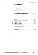
Page 47: ...сания 49 2 Общие правила техники безопасности 49 3 Информация о продукте 50 3 1 Обзор продукта 50 3 2 Варианты продукта 51 3 3 Аксессуары 51 4 Монтаж 52 4 1 Установка заземляющей ленточной скобы 52 4 2 Установка натяжной ленты 54 4 3 Установка нажимных болтов 55 4 4 Уравнивание потенциалов 56 4 4 1 Возможности подключения 56 4 4 2 Установка элемента уравнивания потенциалов 57 5 Техническое обслужи...

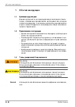
Page 48: ...нформации в случае необходи мости Производитель не несет ответственности за ущерб и повреж дения возникшие в результате несоблюдения указаний данной инструкции Изображения приведены в качестве образца Внешний вид по сле установки может отличаться от представленного на изобра жении 1 3 Типы указателей безопасности ОСТОРОЖНО Вид угрозы Используется для обозначения потенциально опасной ситуации Если ...

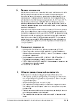
Page 49: ...ны Если заземля ющие ленточные скобы EX BES применяются с другой целью то любые претензии гарантийные иски и требования о возмещении не принимаются 1 5 Стандарты и предписания Категория взрывоопасности согласно директиве ATEX IIC Протестировано согласно VDE 0185 561 1 МЭК EN 62561 1 Элементы молниезащиты LPSC часть 1 Требования к соеди нительным элементам Классификация согласно VDE 0185 561 1 МЭК ...

Page 50: ... 10 12 6 7 11 Рис 1 Обзор продукта 1 Защитный колпачок PA 8 Место подключения потенциала M10 2 Нажимной болт M6 1 9 Поле для маркировки 3 Прижимная скоба 10 Изоляционная пластина 4 Затяжной болт M6 11 Паспортный щиток 5 Натяжная лента V2A 12 Контактный элемент ZnAl 6 Корпус скобы 7 Нажимной болт M6 2 ...

Page 51: ...12 5 kA 25 kA 26 9 300 50 kA N 28 300 50 kA N 300 500 50 kA N 50 kA N Отсутствие искрения при наличии тока грозового импульса 10 350 мкс N Классификация согласно IEC EN 62561 1 2017 3 3 Аксессуары Изображение продукта Наименование Описание Натяжной инструмент Арт 5057 690 Кабельный наконечник Cu Vz DIN 46235 10 16 mm Арт 01924 10 35 mm Арт 01931 10 50 mm Арт 01934 производитель Druseidt GmbH Co KG...

Page 52: ...ости и изоляционные элементы и при необходимости очистить их от загрязнений и устранить повреждения 4 1 Установка заземляющей ленточной скобы 1 С контактной поверхности трубы удалите покрытия и средства защиты от коррозии за исключением горячеоцинкованного слоя 2 Ослабьте фиксацию затяжного болта 4 для демонтажа натяж ной ленты 5 Размер под ключ 10 мм Рис 2 Установка заземляющей ленточной скобы 3 ...

Page 53: ...через корпус скобы 4 Расположите натяжную ленту 5 вокруг трубы и под прижимной пластиной 3 пропустите ее через корпус скобы 6 ОСТОРОЖНО Опасность взрыва Соприкосновение натяжной ленты с контактным элементом в слу чае удара молнии может привести к искрообразованию Установите натяжную ленту параллельно изоляционным пластинам и натяните ее таким образом чтобы она не соприкасалась с кон тактным элемен...

Page 54: ...те края натяжной ленты 5 на длину около 60 мм с по мощью ножниц для резки металла 60 mm Рис 4 Обрежьте края натяжной ленты 2 Ослабьте фиксацию затяжного болта 4 Рис 5 Натяните ленту 3 Установите натяжное устройство на ленту 5 и поверните его пока лента 5 не натянется ...

Page 55: ...яните болт 4 с уси лием 8 Нм 4 3 Установка нажимных болтов 10 mm Рис 6 Установите нажимные болты 1 Поочередно затяните болты 2 7 с усилием 2 Нм таким об разом чтобы пластиковый защитный колпачок 1 приподнялся параллельно трубе Размер под ключ 10 мм Важно Герметику желтого цвета фиксирующему резьбовые соединения требуется около 6 часов для полного отвердевания После монта жа не выкручивайте болты з...

Page 56: ...динительный проводник Материал Поперечное сечение мм Ø мм Многожильный или тонкожильный проводник Медь 16 25 35 50 Проводник круглого сечения Алюминий Медь Оцинкованная сталь Нержавеющая сталь V2A V4A 50 8 78 10 Подключение с помощью кабельного наконечника см 3 3 Аксессуа ры на странице 51 ...

Page 57: ...анного производите лем ОСТОРОЖНО Опасность взрыва Жир пыль загрязнения и царапины на контактных поверхностях или наличие повреждений на изоляционных элементах при ударе молнии могут привести к искрообразованию Перед монтажом необходимо проверить все контактные поверх ности и при необходимости очистить их от загрязнений 17 mm 20 Nm Рис 7 Уравнивание потенциалов 2 Установите кабельный наконечник ряд...

Page 58: ... каждые 2 года Кроме того национальные предписания и стандарты могут содер жать дополнительные требования к техническому обслуживанию которые следует выполнять 6 Демонтаж 1 Снимите заземляющую ленточную скобу с трубы 2 Обновите антикоррозионное покрытие в месте соединения Важно После демонтажа не используйте заземляющую ленточную скобу повторно 7 Утилизация Металлические части как металлолом Пласт...

Page 59: ...рия взрывоопасности см 3 2 Варианты продукта IIC IIB IIA IIIC IIIB IIIA Взрывоопасные зоны см 3 2 Варианты продукта 1 и 2 газы пары туман 21 и 22 пыль Материал PA ZnAl V2A Свойства материала устойчивый к УФ излучению устойчивый к атмосферному воздействию Iimp 10 350 мкм соответствии со стандартом IEC 62561 1 100 кА class H 16 мм Cu многожильный Ø 26 9 мм V2A труба Шина заземления Только внутри пом...

Page 60: ...Holding GmbH Co KG P O Box 1120 58694 Menden GERMANY Customer Service Tel 49 23 71 78 99 20 00 Fax 49 23 71 78 99 25 00 export obo de www obo bettermann com OPTO 180774 Stand 06 2019 HAFA 49540165 Building Connections ...

Reviews: