12
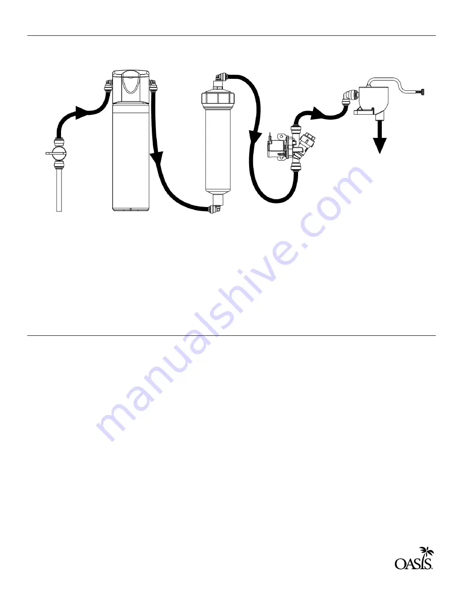
STEP 3B: FILTER INSTALLATION (WITHOUT CHILLER)
STEP 4: Electrical Connections
A.
B.
C.
A.
B.
C.
D.
Plumbing rough-in and wall opening should be prepared as shown in the rough-in
drawing. This drinking water cooler is designed to be operated at a water supply line
pressure of up to 100 PSI (690 kPa). A pressure regulator must be installed in front of the
unit’s water inlet if the pressure (including any possible pressure spikes) could exceed 100
PSI (690 kPa).
Install provided 3/8” O.D. copper tube, strainer, ball valve, and reducer to the building
water supply.
Install tubing as shown above.
A 2 x 4 junction box is provided for the installation of 115V receptacle. This unit is
intended to be connected to a ground fault circuit interrupting (GFCI) device to meet UL
requirements. It is recommended that a flexible conduit be used to supply power to the
junction box and chiller if used. Check the electric current available. Type and voltage
must be the same as listed on the product data plate.
As you put the bottle filler panel assembly in place on the frame assembly, feed the long
green ground wire and the terminals on the power supply cord through the bushings in
the frame assembly.
Attach the long green ground wire to the frame assembly junction box ground then plug
in the bottle filler power cord.
IMPORTANT: Review page 4: QUASAR UV-C LED Operation before proceeding. Failure
to follow the instructions on page 4 can damage the QUASAR module.
Optional In-Line
Filter
Optional
Versafilter III
Inlet Ball Valve
Assy. with
Strainer
Solenoid
Valve
UV-C LED
Summary of Contents for MWEBQ
Page 21: ...21...


