


18
↓
MOTOR SHAFT SEAL REPLACEMENT
HYDRAULIC MOTOR REPAIR KITS
Ace M Series hydraulic motors are high efficiency pressure balanced gear motors. The high efficiency
design prevents replacement of some motor parts if damaged. See Ace Form # HYD-M SERIES for
a listing of available replacement parts. The most common replacement part is the shaft seal which
is listed in the table below for each motor model.
Ace Motor Model
Used on Pump Models
Repair Kit
Ace EDP#
BAC-75-HYD-M16
FMC-650... & FMCWS-650...
RK-BAC-75-M
40138
BAC-75-HYD-M22
FMC-750F...
RK-BAC-75-M
40138
BAC-75-HYD-M25
FMC-750F...
RK-BAC-75-M
40138
BAC-75-HYD-M30
FMC-850F..., FMC-855F..., all -CD
BAC-75-M-FKM
40164
↑
↑
Step 10
↓
Step 6
Step 4
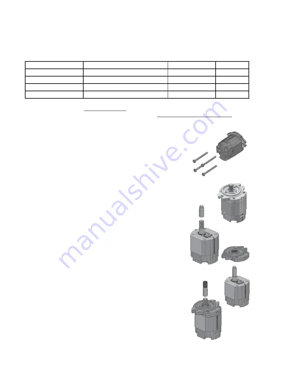
DISASSEMBLY:
1.
Wipe the motor with a clean cloth to remove dirt which could
contaminate the motor.
2.
Note port locations then remove hoses and external fittings.
3.
Mark the motor section joints to indicate orientation of the motor
components.
4.
Remove (4) motor assembly cap screws. Motors with hex head cap
screws require a 17 mm socket. Motors with socket head cap screws
require a 9.5 mm or 3/8” hex key wrench.
5.
Set motor on rear cover with shaft pointing up.
6.
Remove front motor flange by pressing thumbs against shaft end while
pulling up with fingers behind flange ears. Take care to not disturb the
other motor components.
7.
Remove the housing seal O-ring and discard the old flange assembly.
Inspect the motor shaft for grooving or scoring. Moderate to severe
damage in the sealing area may prevent proper sealing and require
motor replacement.
ASSEMBLY: (Note: Do not remove paper tube from seal.)
8.
Place seal installation tool over splined shaft end. Lubricate the tool
and seal lips with clean oil.
9.
Lightly grease housing seal O-ring and place into groove on rear of
new flange.
10.
Carefully place new flange/seal assembly over installation tool and
press down slowly to body. The tool will push the paper tube out.
Note:
Take care to hold the flange level and push evenly on both sides
of the flange.
11.
Discard seal installation tool and paper tube.
12.
Reinstall motor assembly bolts and tighten to 33 ft-lb (45 N-m) torque.
Turn the shaft by hand to ensure the motor turns freely.
13.
Reinstall external motor fittings.
Step 8
Step 11
A new motor seal was implemented in June 2015 for the RK-BAC-75-M kit.
Please refer to Ace Pump Product Update 19
for complete details.
A video of the seal replacement process is available here: www.youtube.com/user/acepump
↓
↑
↑
Summary of Contents for Ace 650 Max Series
Page 2: ...2...