background image

Note:

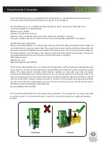
Depending which way the turnstile has been installed the entry/exit may be the opposite way round,

This will not affect the operation in any way.

The table (bottom) relates to the diagram directly below to help you trouble shoot electrical component errors

Example 2

Inputs 1 and 4 are highlighted
Which indicates that the stop
Circuit and raise limit is
Activated as shown in the
Table below

Example 1

There are Several Faults
Texts std in the program
Which will appear on the
PLC screen to help
Diagnose the fault.

If the Screen is not showing
A fault then Press the right
Arrow key once and the
Input screen will appear
As shown in Example 2.

1. Inputs

Input 

Polarity 

Connected to 

Operation when active

I1 

Normally Open 

Free wheel 

Free wheels in both directions

I2 

Normally Open 

Entry signal 

Allows one person through the entry of the turnstile

I3 

Normally Open 

Exit signal 

Allows one person through the exit of the turnstile

I4 

Normally Open 

Entry limit switch 

Switches solenoid off after one person is through

IB 

Normally Open 

Exit limit switch 

Switches solenoid off after one person is through

IC 

Normally Open 

Lock signal 

Locks the turnstile in both positions electrically

ID 

Normally Open 

Spare

IE 

Normally Open 

Spare

2. Outputs

Output: 

Polarity: 

Connected to: 

Operation when active:

Q1 

Normally Open 

Entry Solenoid 

Activates Entry solenoid

Q2 

Normally Open 

Exit Solenoid 

Activates Exit solenoid

Q3 

Normally Open 

Down lights 

Controls down lights(if fitted) from Plc timeclock

Q4 

Normally Open 

Spare

!

Electrical Troubleshooting Guide

D4150

Summary of Contents for D4150

Page 1: ...120 Rotor 100 Duty cycle Made in the Full Heig ht Turns tile D4150...

Page 2: ...cumentation Any other use not specified in this documentation could damage the productand be dangerous The Companydeclines all responsibility for any consequences resulting from improper use of the pr...

Page 3: ...l health arising from the movement of goods from supplier through haulier to the recipient and end user including any home deliveries The project will focus upon the delivery and collection of goods a...

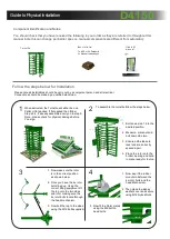
Page 4: ...he Turnstile will either be on a Pallet or flat packed If flat packed then follow Step s 2 4 if already assembled carry on to step 5 Note please check for physical damage before You sign Turnstile Box...

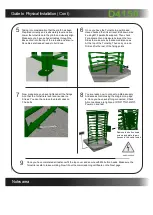
Page 5: ...lastic caps on The bolts 8 You are ready now to connect up Mains supply And access control using the diagram on page 8 Once you have everything connected Check All connections are tight and correct Th...

Page 6: ...ineers Installing Commissioning Equipment Fitted Handover Date Part 2 Existing Installation Items not covered under warranty This certificate Installers Name On Behalf of Address Signature Date of Sig...

Page 7: ...mplying with the appropriate legislation Before carrying out any maintenance to the installation Isolate the mains power supply Make sure you have disconnected Isolated the power before attempting any...

Page 8: ...Connection Terminals Layout PLC 24VDC Power supply D4150...

Page 9: ...Connected to Operation when active I1 Normally Open Free wheel Free wheels in both directions I2 Normally Open Entry signal Allows one person through the entry of the turnstile I3 Normally Open Exit s...

Page 10: ...Top Cog Spring assist requires lubrication Lubricate both items Turnstile Rotor is tight Turnstile is out of square level check turnstile frame is all square level Turnstile Rotor is tight Bottom bea...

Page 11: ...e repair work is carried out on the product This is to achieve two things 1 To keep a history of the product for yourself and your supplier manufacturer 2 To keep an accurate log of any historical or...

Page 12: ...pecification Power Requirement Arms and body Duty Cycle Flow Rate Key Points Access Controls 220 v Single Phase 50 Hz 5 Amps Primed Powder Coated finish 100 continuous duty rating 15 to 22 min in a si...

Reviews: