

- 7 -
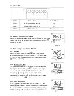
4.5
TDS and Conductivity
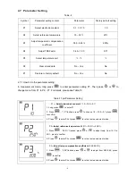
4.5.1.
TDS and conductivity are linear related. The conversion factor is 0.40-1.00. Adjust the factor from
parameter P2.6. The factory default setting is 0.71 and please refer to Section 7.4. The meter only needs to
be calibrated in Conductivity mode, then after calibration of conductivity, the meter can switch from conductivity
to TDS.
4.5.2.
Adjust TDS conversion factor in parameter setting P4 according to the data collected during testing and
experience. Table – 10 lists some commonly used Conductivity and TDS conversion factors. This is for your
reference only.
Table – 10 Conductivity and TDS conversion factors
Conductivity of solution
TDS conversion factor
0-100 μS/cm
0.60
100-1,000 μS/cm
0.71
1-10 mS/cm
0.81
10-100 mS/cm
0.94
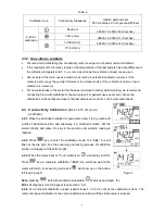
4.6
Sample Test
4.6.1.
Rinse conductivity electrode in distilled or pure water, dry it, and submerge it in the sample solution. Stir
the solution briefly and allow it to stay in the sample solution until a stable reading is reached and
icon
appears on LCD, then get the reading value, which is the conductivity value of the solution.
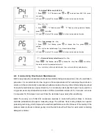
4.6.2.
During the process of calibration and measurement, the meter has self-diagnosis functions, indicating
the relative information as below: Table – 8.
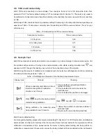
Table – 8 Self-diagnosis information of conductivity measurement mode
Display Icons
Contents
Checking
Wrong conductivity calibration solution or
the meter recognition of calibration
solution is out of range.
1. Check whether conductivity calibration
solution is correct.
2. Check whether the meter connects the
electrode well.
3. Check whether the electrode is damaged.
Press
key when measuring value is
not stable during calibration.
Press
key
after
icon appears.
During calibration, the measuring value
being unstable for over 3 minutes.
1. Shake the electrode to eliminate bubbles in
electrode head.
2. Replace with new conductivity electrode.
4.6.3.
Factory default setting
For factory default setting, please refer to parameter setting P7 (Section 4.7.2). With this function, all calibration
data is deleted, and the meter restores to the theory value. Some functions restore to the original value. When
calibration or measurement fails, please restore the meter to factory default setting and then perform re-
calibration or measurement. Please note once set the factory default, all the data deleted will be irretrievable.


