- 2 -
- 3 -
50~400Hz
14.8V-52.2V(4S LiPo-12S LiHV)
150A (5 seconds, 20℃, cooling air 5m/s)
100A (180 seconds, 20℃, cooling air 5m/s)
None
(Input signals are insulated by a photocoupler.)
Fixed 0~25
°
adjustable by 1
°
Selectable : 8kHz, 16kHz, 32kHz
ON/OFF
OFF or adjustable 0~100% by 2%
Adjustable 0~2.0 sec. by 0.1 sec.
OFF or adjustable 40~120% by 5%
ON/OFF
Automatic/Set value, Stop Position/Maximum Throttle Position
37mm(W) x 95mm(L) x 16mm(H)
125g including lead wires and 4φ connectors
13AWG, 100mm length, covered by silicone tube
14AWG, 100mm length, covered by silicone tube
22AWG, 3-Wire (
Black-red-white
) 240±10mm
22AWG, 3-Wire (
Brown-red-orange
) 140±10mm
The parameters can be set with OCP-3 ESC programmer
Start protection/Low voltage cutoff/Non signal cutoff/
Overheat protection/Anti-spark protection/
Automatic battery cell quantity recognizing system
OCA-3100HV
OCA-3070HV
OCA-3100HV/OCA-3070HV
OCA-3100HV
High-Resolution
OPT
O55V
12S
to be connected to a brushless
motor
[OCA-3100HV / OCA-3070HV SPECIFICATIONS]
Input signal period
Voltage Range
Maximum peak current
Maximum current
Intemal BEC
Advance Timing
PWM Frequency
Active Freewheel
Braking force setting
Brake speed setting
Current limit
Governor
Throttle mode
Outside dimension
Weight
Batterie Leads
Motor Leads
Input signal leads
Setting leads
Setting
Protective function
Edit buttons
Connecting the programmer
Operation of the edit buttons
Setting items
Battery type
Battery Cut-off
Cut-off type
Motor timing
Acceleration
Drive Frequency
Reverse Rotation
Brake Force
How to set the ESC using OCP-3
Battery type
Setting choice : LiPo or NiCd
Default setting : LiPo
Battery Cut-off
Setting range : 2.9V
~3.2V
Default setting : 3.2V
Cut-off type
Setting choice : Reduce power by 50% or
Switch OFF (stop the motor)
Default setting : Reduce power by 50%
Setting range : 0
~
25°
Motor Timing
Default setting : 12°
Acceleration
Setting range : 20
~200
Default Setting : 100
Start Power
[preparation] Solder suitable connectors to lead wires (red, black) of the ESC. Use a piece of shrink tube for insulation at each connecting
point. Solder suitable female connectors to the three lead wires of the ESC, which are to be connected to three male connectors of the
brushless motor. Use shrink tubes for insulation at connecting points.
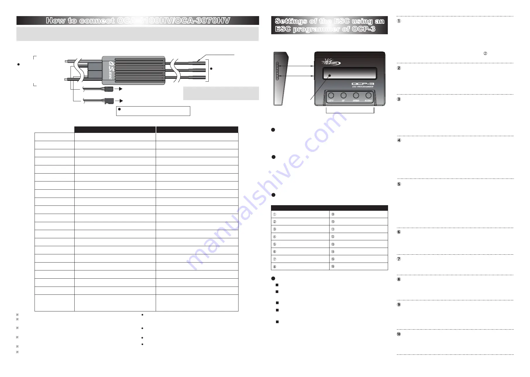
How to connect OCA-3100HV/OCA-3070HV
How to connect OCA-3100HV/OCA-3070HV
The drawing below shows connection of OCA-3100HV/OCA-3070HV.
Positive side
(+, red)
Connect each wire to a
batteries; positive to positive,
negative to negative.
Do not make the polarity
reversed.
Negative side
(-, black)
Brown-red-orange wire
Black-red-white wire
to be connected to change the
program using OCP-3
to be connected to a throttle
channel of a transmitter
A receiver battery should be used
independently to connect to a receiver.
Solder suitable female connectors to the
three lead wires. Use a piece of shrink tube
for insulation to each connecting point.
Start protection: the device stops the motor when it is started unintentionally.
the device stops the motor when it loses control, or before
incoming voltage.
Low voltage cut-off:
the device cut off the ESC when no signal from the transmitter is
detected.
No signal cut-off:
the device regulate the output to protect FETs when
temperature of ESC rapidly rises due to overload.
Protection against overheating:
the device reduces sparks when the ESC is connected to a battery.
Anti-spark:
the device detects number of battery cells
automatically.
Automatic detection of battery cells:
In order to maintain an optimum current and rated current of the ESC, cooling air;
propeller slip stream and natural air of atmospheric temperature 20℃ or lower at
wind speed (5m/s or more) over the entire heat sink is required.
The maximum performance limit of ESC greatly changes depending on environmen
-
tal factors such as atmospheric temperature and humidity.
Battery voltage is detecting system. A buzzer tells you how many cells in a battery.
The active free-wheeling reduces heat of the ESC generated during operation, which
is a waste.
Settings of the ESC using an
ESC programmer of OCP-3
Settings of the ESC using an
ESC programmer of OCP-3
With OCP-3 (optional), you can set the ESC more quickly and
easily.
Connect OCA-3100HV/OCA-3070HV to the ESC socket of
OCP-3, and a battery (4.8
〜
7.4V) to the BATT socket of
OCP-3.
Select a setting item by pressing the UP or the DOWN
button.
The LEFT and the RIGHT buttons are to select each item in
the setting or to change the setting.
The following items can be set with OCP-3.
Setting items (model type: airplane)
Brake Speed
Start Power
Active Freewheel
Current Limit
Governor settings
Motor Type
Throttle Mode
Restore Default
Disconnect the battery from the ESC.
Connect a battery (4.8
〜
7.4V) to the socket BATT socket of
OCP-3.
Select a setting item by pressing the UP and the DOWN buttons.
Select or change the setting item by pressing the LEFT and the
RIGHT buttons.
Any chosen value of setting is memorized in the ESC automati-
cally one by one without requesting you any further action to
memorize the value in the ESC.
Select the battery type and number of cells with the LEFT and
the RIGHT buttons.
Setting a number of the battery cells: AUTO
In case NiCd is selected, pass the setting item .
The cut-off voltage is automatically fixed at 50% of an initial value.
Set the cut-off voltage when you select LiPo battery with the
LEFT and the RIGHT button.
Select how to cut off the power when voltage of the battery drops
to the set value of cut-off voltage with the LEFT and the RIGHT
buttons.
For 2~4-pole motors, usually we recommend 0~5°
Set the value within the range shown below.
for inner rotor type : 0
~
10° for outer rotor type : 10
~
25°
Select the advance timing with the LEFT and the RIGHT buttons.
This is the speed at which the ESC reaches the top speed.
Select the acceleration value with the LEFT and the RIGHT
buttons.
The setting value is 50 or lower in case a motor is turned
ON/OFF by an on-board switch of a transmitter such as gliders.
Drive Frequency
Setting choice : 8kHz / 16kHz / 32kHz
Select the value with the LEFT and the RIGHT buttons.
We recommend 32kHz for 10-pole or less motors.
Reverse Rotation
Setting choice : Normal / Reverse
Select the direction of rotation with the LEFT and the RIGHT buttons.
Brake Force
Setting range : OFF
~100%
Default Setting : OFF
Set the value with the LEFT and the RIGHT buttons.
Brake Speed
Setting range : 0
~
2.0 seconds
Default Setting : 0.1 second
Set the value with the LEFT and the RIGHT buttons.
Setting choice : Super Soft / Very Soft / Soft / Hard
Default Setting : Soft
Select the start power with the LEFT and the RIGHT buttons.
50~400Hz
14.8V-52.2V(4S LiPo-12S LiHV)
90A (5 seconds, 20℃, cooling air 5m/s)
70A (180 seconds, 20℃, cooling air 5m/s)
None
(Input signals are insulated by a photocoupler.)
Fixed 0~25
°
adjustable by 1
°
Selectable : 8kHz, 16kHz, 32kHz
ON/OFF
OFF or adjustable 0~100% by 2%
Adjustable 0~2.0 sec. by 0.1 sec.
OFF or adjustable 40~120% by 5%
ON/OFF
Automatic/Set value, Stop Position/Maximum Throttle Position
37mm(W) x 95mm(L) x 16mm(H)
124g including lead wires and 4φ connectors
13AWG, 100mm length, covered by silicone tube
14AWG, 100mm length, covered by silicone tube
22AWG, 3-Wire (
Black-red-white
) 240±10mm
22AWG, 3-Wire (
Brown-red-orange
) 140±10mm
The parameters can be set with OCP-3 ESC programmer
Start protection/Low voltage cutoff/Non signal cutoff/
Overheat protection/Anti-spark protection/
Automatic battery cell quantity recognizing system
Connector (optional)
(not for FAI F3A
competitions)
No electronic sound is emitted from the OCP-3
and the motor when you press the buttons.
※
LCD
ESC
BATT
(4.8V〜7.4V)