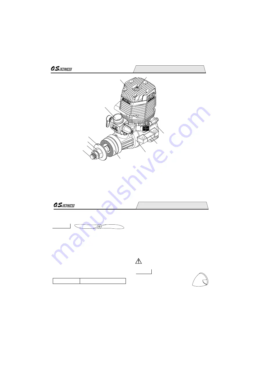
background image

10

BASIC ENGINE PARTS

Cylinder head

Carburetor Type 61A-BE 

Crankshaft

Propeller nut

Propeller washer

Drive Hub

Crankcase

Cover Plate

Glowplug

Beam Mount

Lock nut

11

Tools,  accessories,  etc.  The  following  items 
are necessary for operating the engine.

BEFORE STARTING

The choice of propeller depends on the design 
and weight of the aircraft and the type of flying 
in  which  you  will  be  engaged.  Determine  the 
best  size  and  type  after  practical 
experimentation.  As  a  starting  point,  refer  to 
the  props  listed  in  the  accompanying  table. 
Slightly  larger,  or  even  slightly  smaller,  props 
than  those  shown  in  the  table  may  be  used, 
but  remember  that  the  propeller  noise  will 
increase,  due  to  higher  rpm  or  if  a  larger-
diameter/lower-pitched prop is used.

Propellers

13x9-10, 14x6-8, 15x6

Sport

Never touch, or allow any object to come into 

contact with, the rotating propeller and do not 

crouch over the engine when it is running.

Reminder!

Warning:
Make  sure  that  the  propeller  is  well 
balanced.  An  unbalanced  propeller  and/or 
spinner  can  cause  serious  vibration  which 
may weaken parts of the airframe or affect 
the safety of the radio-controlled system.
DO NOT forget the WARNINGS and NOTES 
on  propeller  and  spinner  safety  given  on 
front pages.

Since the 75AX-BE is intended to 
be started with an electric starter, 
the  addition  of  a  spinner 
assembly  for  centering  the  starter  sleeve  is 
desirable.  Use  a  heavy-duty,  well  balanced 
spinner either of metal or plastic.

Spinner

It is suggested to use propellers which develop 
maximum  r.p.m.  of  8,500~9,500  so  that  you 
may  enjoy  pleasant  exhaust  sound  keeping  it 
low.

Summary of Contents for MAX-75AX-BE

Page 1: ...c are accessible for checking at the same time 1 2 6 7 8 9 10 20 21 22 28 31 15 17 SAFETY INSTRUCTIONS AND WARNINGS ABOUT YOUR O S ENGINE ENGINE CONSTRUCTION NOTES WHEN APPLYING AN ELECTTRIC STARTER ABOUT THE ENGINE BASIC ENGINE PARTS BEFORE STARTING INSTALLATION INSTALLATION OF THE STANDARD ACCESSORIES FUEL TANK LOCATION MIXTURE CONTROLS GLOWPLUG CONTENTS STARTING RUNNING IN IDLING ADJUSTMENT CHA...

Page 2: ...engine in an en closed space Model engines like auto mobile engines exhaust deadly carbon monoxide Run your engine only in an open area Model engines generate considerable heat Do not touch any part of your engine until it has cooled Contact with the muffler silencer cylinder head or exhaust header pipe in particular may result in a serious burn Never touch or allow any object to come into contact...

Page 3: ...s check the tightness of the propeller nut and retighten it if necessary before restarting the engine Also check the tightness of all the screws and nuts before restarting the engine If you install a spinner make sure that it is a precision made product and that the slots for the propeller blades do not cut into the blade roots and weaken them Preferably use an electric starter The wearing of safe...

Page 4: ...eparing your model for flight If you have to carry the model to the take off point with the engine running be especially cautious Keep the propeller pointed away from you and walk well clear of spectators Warning Immediately after a glowplug ignition engine has been run and is still warm conditions sometimes exist whereby it is just possible for the engine to abruptly restart if the propeller is c...

Page 5: ...r Retaining Screw M4x40 2pcs ABOUT THE ENGINE The MAX 75AX BE has been developed and designed to use O S Bio Ethanol fuel only Therefore some parts are different from those of the MAX 75AX that use conventional methanol based glow fuel Also special attention is required in it s handling This engine has been developed based on the MAX 75AX to use only O S Bio Ethanol fuel Itdevelopsenoughpowertofly...

Page 6: ...f a larger diameter lower pitched prop is used Propellers 13x9 10 14x6 8 15x6 Sport Never touch or allow any object to come into contact with the rotating propeller and do not crouch over the engine when it is running Reminder Warning Make sure that the propeller is well balanced An unbalanced propeller and or spinner can cause serious vibration which may weaken parts of the airframe or affect the...

Page 7: ...ia and pitch purposely so that conventional glow plugs may not be installed 13 1 2V 1 5V S GLOWPLUG IGNITER Commercialy available handy glowplug heater in which the glowplug battery and battery leads are integrated Alternatively one of the purpose made manual or electric fuel pumps may be used to transfer fuel directly from your fuel container to the fuel tank FUEL PUMP Manual Electric Electric St...

Page 8: ...heavy and rigid as possible engine mounting for highest performance and safe running Conventional wooden mounting beams should be of rigid hardwood and of at least 15mm or 5 8 in square section Use at least 3mm steel screws such as Allen type with locknuts for bolting the engine to the bearers INSTALLATION CORRECT Top surfaces are in the same plane INCORRECT Front view Side view Re align the surfa...

Page 9: ...hers and locknuts for bolting the engine to the bearers O S Radial Motor Mount A special O S radial motor mount Code No 71905200 is available as an optional extra for use where firewall type mounting is required 17 THROTTLE LINKAGE Before connecting the throttle to its servo make sure that the throttle arm and linkage safely clear any adjacent part of the airframe structure etc as the throttle is ...

Page 10: ...ALLATION OF THE STANDARD ACCESSORIES 19 INSTALLING SILENCER E40400 Silencer Model engines generate considerable heat Do not touch any part of your engine until it has cooled Contact with the muffler silencer cylinder head or exhaust header pipe in particular may result in a serious burn Keep your hands and face away from exhaust gas or you will suffer a burn Reminder The exhaust outlet of the sile...

Page 11: ... the tank when held vertically Use a suitable length of best quality 5mm OD x 2 5mm ID silicone tubing for fuel tubing Fuel line weight should be 10mm away from the tank bottom Locate the fuel tank so that the center line of the tank is 10 to 15mm below the center line of the needle valve 21 Attention to tank height Plug commercially available Approx 15mm Approx 10 15mm needle valve Center Line Fu...

Page 12: ... responses will not be obtained Adjust it at optimum position after the running in is completed 23 GLOWPLUG The role of the glowplug Glowplug life Be sure to disconnect the plug leads when adjusting the needle valve at higher r p m range Do not run the engine too lean and do not leave the battery connected while adjusting the needle With a glowplug engine ignition is initiated by the application o...

Page 13: ...ads to glowplug Check that the needle valve is closed Do not overtighten Now open the needle valve counter clockwise 4 5 5 turns to the starting setting 3 4 Open the throttle approx one quarter This is to avoid unnecessarily high r p m when the engine starts Turn needle valve clockwise to close for leaner mixture Turn needle valve counter clockwise to open for richer mixture Mark Close Open Fully ...

Page 14: ...g The 75AX BE requires some patience when adjusting so become acquainted with the needle valve setting procedure described above Open the needle valve 1 2 1 turn when restarting the engine after the flight Then start the engine and adjust the needle valve after warming the engine well up Longer warning up time is required when the temperature is low while shorter warning up time is required when t...

Page 15: ... called for and can be carried out with the engine installed in the model The process is as follows 1 29 Re start and adjust the needle valve so that the engine just breaks into a two cycle from four cycle operation then make three or four flights avoiding successive nose up flights 3 During subsequent flights the needle valve can be gradually closed to give more power However if the engine shows ...

Page 16: ...ugh this is a two stroke engine it fires like a four stroke at these rich needle valve settings i e ignition of the fuel charge takes place at every fourth stroke of the piston instead of at every second stroke 1 2 3 4 5 6 7 31 IDLING ADJUSTMENT CHART Start the engine Make sure that the throttle is fully open Adjust the needle valve Close the throttle gradually Set the idle speed Open the throttle...

Page 17: ...ixture is excessively lean the r p m will increase gradually then the engine stop the screw clockwise gradually until the engine retains full power cleanly when the throttle is reopened 33 REALIGNMENT OF MIXTURE CONTROL VALVE SUBSEQUENT STARTING PROCEDURE Once the optimum needle valve setting has been established see page 30 Needle valve adjustment diagram the procedure for starting may be simplif...

Page 18: ... action 2 3 1 2 3 3 3 3 2 Voltage too high or too low Re check and readjust referring to BEFORE STARTING Continue applying an electric starter If the engine dos not start after more than 4 tries disconnect the current to the glowplug and leave for a few minutes then re energize plug and apply starter If the engine still does not start remove glowplug and pump out excess fuel by applying the starte...

Page 19: ...n these filters periodically 37 Do not close the needlevalve and mixture control valve too far as this will cause a lean setting and over heating of the engine Always adjust the needlevalve slightly on the rich side of peak rpm Do not leave unused fuel in the engine at the conclusion of a day s flying Accepted practice is to cut off the fuel supply while the engine is still running at full throttl...

Page 20: ...04010 27414010 27403000 27406000 27917000 27405000 27482020 45910100 27408010 29320000 27731000 27401000 29030001 27402000 27414020 27407000 71668100 72200080 27425000 29122540 27425300 22681957 26625210 Cylinder Head Head Gasket Cylinder Piston Assembly Piston Pin Piston Pin Retainer 2pcs Connecting Rod Carburetor Complete Type 61A BE Lock Nut Set Drive Hub Thrust Washer Crankshaft Ball Bearing F...

Page 21: ...7482120 45581820 22681953 25781970 24981837 26381501 27381940 26711305 46215000 25081700 CARBURETOR PARTS LIST Description Code No No Specifications are subject to alteration for improvement without notice Throttle Lever Assembly Assembly Screw Carburetor Rotor Mixture Control Valve Assembly O Ring L 2pcs O Ring S 2pcs Carburetor Body Roter Guide Screw Fuel Inlet No 1 Needle Assembly O Ring 2pcs S...

Page 22: ...0mm 35 0mm 42 0mm Width Screw hole pitch 71905200 71531010 NON BUBBLE WEIGHT S 45910200 PROPELLER LOCKNUT SET For Spinner 5 16 M4 43 71521000 M3x8 79871110 M3x16 79871160 The specifications are subject to alteration for improvement without notice LONG SOCKET WRENCH WITH PLUG GRIP CAP SCREW SETS 10pcs sets 72403050 SUPER FILTER L 79870040 M4 M4 55500003 79870030 M3 M3 55500002 LOCK WASHER 10sets BL...

Page 23: ...103 29 1 52 38 5 54 1 42 35 7 57 7 12 29 cc 0 75 cu in 25 8 mm 1 016 in 23 5 mm 0 925 in 2 300 10 000 r p m 1 2 ps 1 22 hp 10 000r p m 583 g 20 56 oz 178 g 6 28 oz E 4040 Silencer C Copyright 2008 by O S Engines Mfg Co Ltd All rights reserved Printed in Japan 60092050 061101 TEL 06 6702 0225 FAX 06 6704 2722 6 15 3 Chome Imagawa Higashisumiyoshi ku Osaka 546 0003 Japan URL http www os engines co j...

Reviews: