background image

12

Since the FS-70 ULTIMATE


is intended to be started with an 

electric starter, the addition of a spinner assembly for 
centering the starter sleeve is desirable. In this case, optional 
locknut sets are available from O.S. Propeller Locknut Set for 
Spinner (Code No. 45810200) Propeller Locknut Set for Tru 
Turn Spinner (Code No. 45810300).

PROPELLER & SPINNER ATTACHMENT

Ream the propeller shaft hole to 6.5mm bore with an 
appropriate reamer, checking that the hole is exactly 
centered.

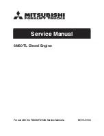
Install the prop to the engine shaft, followed by the retaining 
washer and prop nut and tighten firmly with a 12mm 
wrench.

There is a risk, particularly 
with powerful four-stroke 
engines, of the propeller flying 
off if the prop nut loosens due 
to detonation ("knocking") in 
the combustion chamber when 
the engine is operated too 
lean, or under an excessively 
heavy load. 

Obviously, this can be very hazardous. To eliminate such 
dangers, the O.S. Safety Locknut Assembly was devised. 
Install this as follows:

Lock Nut

Propeller Washer

Propeller Nut

1.

2.

3.

Two adjustable controls are provided on these carburetors. 
They are as follows:

TYPE 60U CARBURETOR

The Needle Valve

This is used to establish the fuel/air 
mixture strength required for full 
power when the throttle is fully open.

The sequence in which these controls are adjusted is 
explained in the succeeding sections, under Starting, 
Running-in and Idling Adjustment.

Add the special tapered and slotted locknut and secure 
with a 10mm wrench while holding the prop nut with the 
12mm wrench.

Needle Valve

Mixture
Control Screw

Spinners retained by a nose bolt cannot be used with this 
Locknut.

The Mixture Control Screw

This is used to establish the mixture strength required for 
steady idling and a smooth transition to medium speeds. 
(The varying mixture strength required between part-throttle 
and full-throttle running is automatically adjusted by coupled 
movement of the throttle.)

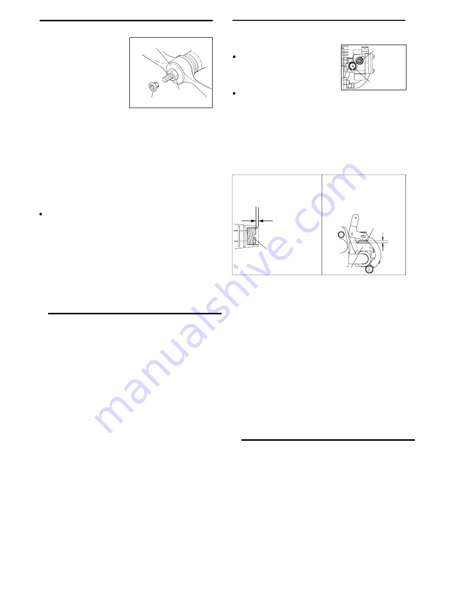
BASIC POSITION OF THE
MIXTURE CONTROL SCREW

The basic position is
1/2 turn screwed in 
position from the flat 
with the body face.

Mixture Control Screw

IDLING POSITION OF THE
THROTTLE VALVE

The idling position is where 
the throttle valve comes out 
approx. 1mm from the body 
face.

Carburetor Body

Throttle Valve

Approx. 1mm

13

STARTING

The FS-70 ULTIMATE


is not equipped with manual choke 

controls, as they are intended for use with an electric starter only. 

A high-torque electric starter not only makes starting the engine 
much easier, it dispenses with the need for a choke valve by 
turning the engine over fast enough to cause the fuel pump to 
prime the cylinder automatically.
Starting procedure is as follows:

Check that the current to the glowplug is switched off.

Check that the polarity of the starter battery leads rotates the 
engine counter-clockwise when viewed from the front.

Open the needle-valve approx. 2 turns from the fully closed 
position and temporarily set the throttle in the fully open 
position.

Apply the starter and press the starter switch for 5-6 
seconds, or until fuel is seen to emerge from the exhaust 
outlet, indicating that the cylinder is now primed.

Close the throttle-arm to within 15-20

°

 of the fully closed 

position and slowly turn the prop "backwards" (clockwise) by 
hand until it is arrested by compression.This is to enable the 
kinetic energy of the prop to subsequently assist the starter 
through the compression stroke to start the engine.

Energize the glowplug and apply the starter. If the starter 
fails to rotate the engine completely, this may be due to the 
cylinder being over-primed, or to  the starter battery being 
insufficiently charged.

RUNNING-IN ("Breaking-in")

For long life and peak performance, every engine needs 
special treatment when new, known as "running-in" or 
"breaking-in". This is a process during which the engine is 
operated under strictly controlled conditions at the beginning 
of its life, in order to avoid the risk of immediate damage to 
certain components through becoming overheated or stressed 
and to help working surfaces to become smoothed and 
aligned for maximum mechanical efficiency thereafter.
With some engines, this can require a tediously protracted 
period of bench running, but, as O.S. engines are 
manufactured to fine tolerances and from the finest quality 
materials, a relatively brief running-in period is sufficient and 
can be completed with the engine installed in the aircraft. 
The recommended procedure is as follows :

1.

2.

3.

4.

5.

6.

Check these conditions and, instead of pressing the starter 
button after applying the starter, have the starter spinning 
before applying it to the engine, to give it a "running start".
When the engine starts, slowly open the throttle, leaving 
the needle-valve at its rich starting setting to promote cool 
running conditions.
However, if the engine slows down because the mixture is 
excessively rich, the needle-valve may be closed a little to 
speed it up until it runs evenly.

Now disconnect current to the glowplug and gradually close 
the needle-valve so that the engine rpm increases. Make 
adjustments to the needle in small steps. Abrupt changes 
at this stage are likely to cause the engine to stall. Restart 
the engine by simply applying the starter with the glowplug 
re-energized and the throttle at its starting setting.

7.

8.

Summary of Contents for FS-70 Ultimate

Page 1: ...control equipment etc are accessible for checking at the same time 1 2 4 5 6 7 8 9 10 11 12 13 14 SAFETY INSTRUCTIONS AND WARNINGS ABOUT YOUR O S ENGINE INTRODUCTION INSTALLING THE GLOWPLUG INSTALLATION FUEL TANK LINES EXHAUST HEADER PIPE AND SILENCER THROTTLE LINKAGE NEEDLE VALVE EXTENSION CARE OF FUEL PUMP AND REGULATOR PROPELLERS GLOWPLUGS FUEL PROPELLER AND SPINNER ATTACHMENT TYPE 60U CARBURET...

Page 2: ...your engine in an enclosed space Model engines like automobile engines exhaust deadly carbon monoxide Run your engine only in an open area Model engines generate considerable heat Do not touch any part of your engine until it has cooled Contact with the muffler silencer cylinder head or exhaust header pipe in particular may result in a serious burn 3 NOTES This engine was designed for model aircra...

Page 3: ... glowplug ignition engine has been run and is still warm conditions sometimes exist whereby it is just possible for the engine to abruptly restart if the propeller is casually flipped over compression WITHOUT the glowplug battery being reconnected Remember this if you wish to avoid the risk of a painfully rapped knuckle NOTES 5 INTRODUCTION Rocker Cover Cylinder Head Push Rod Cover Drive Hub Prope...

Page 4: ... nut firmly down onto first nut Tighten this nut first Steel washer 3mm steel nuts 3mm steel screw Spring washer or lock washer 15mm min 15mm min Hardwood such as cherry or maple Spring washer 3mm steel Allen screw 7 FUEL TANK LINES 10 15mm A fuel tank of approximately 300cc capacity is suggested This allows up to 12 13 minutes flying time dependent upon the type of fuel used the size of the prope...

Page 5: ...throttle stick is in its fully open position Carefully align the appropriate holes in the throttle arm and servo horn so that they move symmetrically and smoothly through their full travel Install these in the following sequence Screw the header pipe into the cylinder head until it bottoms then unscrew sufficiently to achieve the desired exhaust angle and tighten the locknut securely with a 14mm w...

Page 6: ...small percentage 5 30 of nitromethane for improved flexibility and power The carburetor is adjusted at the factory for a fuel containing 20 lubricant and 15 nitromethane Some commercial fuels also contain coloring additives as an aid to fuel level visibility In some cases these additives have indicated slightly negative effects on performance We would suggest that you use such fuels only if you ar...

Page 7: ... fast enough to cause the fuel pump to prime the cylinder automatically Starting procedure is as follows Check that the current to the glowplug is switched off Check that the polarity of the starter battery leads rotates the engine counter clockwise when viewed from the front Open the needle valve approx 2 turns from the fully closed position and temporarily set the throttle in the fully open posi...

Page 8: ...ightly rich 30 45 from the highest r p m setting Close the throttle to the idle position Allow the engine to idle for about 5 seconds then reopen the throttle The engine should accelerate smoothly back to full speed If instead the engine responds sluggishly and emits an excess of white smoke from the exhaust the idle mixture is too rich Turn the mixture control screw approx 45 clockwise to lean th...

Page 9: ...ount of running time a loss of power is detected or if the engine has been disassembled for repair these clearances should be checked and reset as necessary VALVE ADJUSTING The kit comes in a plastic case and includes Code No 72200060 Feeler gauge 0 1mm Hex key 1 5mm Wrench 5mm 17 Re tighten locknut while holding adjusting screw stationary Fig 5 4 Hold at the screw head Fig 5 Tighten Locknut Remov...

Page 10: ...le valve assembly from the carburetor and remove any foreign matter that has accumulated in this area See photo If these precautions are neglected restriction of fuel flow may cause the engine to cut out or the fuel air mixture to become too lean causing the engine to overheat The use of modern high performance alcohol based model engine fuels while promoting cooler running improved anti detonatio...

Page 11: ... Head Screw N Round Head Screw S Set Screw C M3x12 C M3x16 C M2 6x8 C M2 6x8 F M2 6x6 2 30 2 3 3 1 3 2 4 4 1 4 2 5 5 4 5 3 5 2 5 1 6 7 8 9 1 10 11 12 13 14 15 17 18 19 20 21 22 30 1 30 2 23 24 25 26 6 1 6 2 6 3 6 4 28 29 C M3 5x20 16 24 27 30 31 32 34 33 C M2 6x18 18 1 18 2 18 3 ...

Page 12: ...10 11 12 13 14 15 16 17 44704200 44714300 45961400 45961410 45761600 44753000 44753100 45761200 44750000 44750100 45960210 45960310 45960400 44751000 44751100 45960210 45960310 45960400 44704100 44704000 45515000 44769400 44781000 44714100 29503400 44703200 45906000 44705000 44703100 18 18 1 18 2 18 3 19 20 21 22 23 24 25 26 27 28 29 30 30 1 30 2 31 32 33 34 44782000 44782160 45771000 22681957 447...

Page 13: ... 0mm 0 748in 2 000 15 000r p m 1 2ps 11 000r p m 455g 16 0oz JAPAN JAPAN 54 35 4 59 5 34 5 24 1 50 2 29 6 35 1 87 4 18 105 4 20 49 5 45 58 9 UNF1 4 28 4 3 7 92 26 7 45 20 39 5 142 25 6 without Locknut Drive Hub Woodruff Key F 4020 U Silencer Assembly 527 3g 18 61oz 51g 1 8oz With F 4020 U Silencer Assembly F 4020 U Silencer Assembly 24 MEMO ...

Page 14: ...ed Printed in Japan TEL 06 6702 0225 FAX 06 6704 2722 6 15 3 Chome Imagawa Higashisumiyoshi ku Osaka 546 0003 Japan 60091400 090304 URL http www os engines co jp U N E Q U A LLED QUALITY PRECISION PERFOR M A N C E E S T A BLISHING THE STANDARDS OF EXCELLE N C E ...

Reviews: