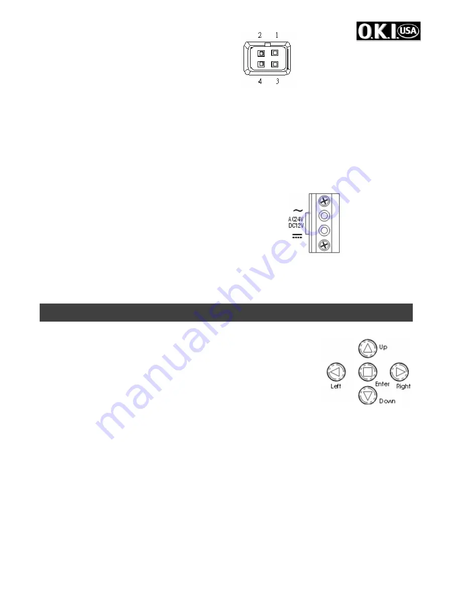
- 4 -
1.Red --- power
3.White --- video
2.NC
4.Black
---
shielded
Auto iris lens without EE amp. (DC Type)
Set the lens selector to “DD” position.
Connector cable leads
1. Damping coil (-) 3. Driving coil (+)
2. Damping coil (+) 4. Driving coil (-)
F. Video output terminal (BNC)
This connector is used to connect with VIDEO IN connector of monitor.
G. On-Screen Display keypad
H. Slide out for control panel
I. Power pilot LED
J. 12V DC / 24V AC Block Terminal
This terminal accepts DC 12V (Non-polarity) or 24V AC.
The other model: 85 ~ 265V AC.
K.
OSD Remote control connector (MINI JACK)
L.
The Device for sensing brightness level (for D/N function).
4. USER OSD SETTING
SETTING SWITCHES AND FUNCTIONS
1.UP
button –This button is used to move the cursor upwards. Use
this button to select item.
2.LEFT
button –This button is used to move the cursor left. Use to
select or adjust the parameters of the selected item.
3.RIGHT
button –This button is used to move the cursor to the right.
Use to select or adjust the parameters of the selected item.
4.DOWN
button –This button is used to move the cursor downwards. Use this button to select
item.
5.ENTER
button – Press this button to display the setting menu, if the selected item has its own
menu; press this button to enter sub menu.
PC control
For Windows 95/98/ME/2000/XP
1. Insert the floppy into diskette drive
2. Execute OSD_CONT.EXE
3. A keypad icon will be displayed on the screen
4. Use mouse to point the icon for on-screen-display setting
12V DC/24V AC MODEL
Summary of Contents for WDS-HDR1527DN
Page 14: ... 14 ...


