


Enhanced Serial Communication Interface (eSCI)
PXN20 Microcontroller Reference Manual, Rev. 1
Freescale Semiconductor
31-49
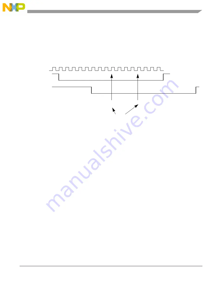
If fast bit error detection bit FBR in the eSCI Control Register 2 (eSCI_CR2) is set, the eSCI compares the
transmitted and received data streams while the transmitter is active (not idle). Once a mismatch between
the transmitted data and the received data is detected, the bit error flag BERR is set.
To adjust to different bus loads, the sample point at which the incoming bit is compared to the transmitted
bit can be selected with the BESM bit in the eSCI Control Register 2 (eSCI_CR2). If
eSCI_CR2[BESM] = 1, the comparison is performed with sample RS13. Otherwise, it is performed with
RS9, as shown in
. See
Section 31.4.5.3.13, Bit Sampling.
Figure 31-43. Timing Diagram Fast Bit Error Detection
NOTE
To calculate the exact position of the sample point with regard to the RX pin,
the delays through the pads and the two Bus Clock cycle delay through the
input synchronizer also needs to be taken into account.
31.4.6.5.5
Slave-Not-Responding-Error Detection
The Slave-Not-Responding-Error is defined in LIN Specification Package Revision 1.3; December 12,
2002; 6 ERROR AND EXCEPTION HANDLING. The LIN specification requires that a
NO_RESPONSE_ERROR has to be detected if a message frame is not fully completed within the
maximum length T
FRAME_MAX
by any slave task upon transmission of the SYNCH and IDENTIFIER
fields. The maximum frame length T
FRAME_MAX
is defined in LIN Specification Package Revision 1.3;
December 12, 2002; 3.3 LENGTH OF MESSAGE FRAME AND BUS SLEEP DETECT, as
Eqn. 31-11
where N
DATA
is the number of data byte fields of the message frame.
The STO interrupt flag in the eSCI Interrupt Flag and Status Register 2 (eSCI_IFSR2) is set if a LIN RX
frame was not fully received in the amount of time specified in the timeout value field TO in the eSCI LIN
Transmit Register (eSCI_LTR). The time period starts with the falling edge of the transmitted LIN break
character and is specified in units of transmit bits.
To achieve LIN compliant Slave-Not-Responding-Error detection, the timeout value TO in the eSCI LIN
Transmit Register (eSCI_LTR) field has to be set to T
FRAME_MAX
when a LIN RX frame is initiated.
Output Transmit
Shift Register
1
2
3
4
5
6
7
8
9
10 11 12 13 14 15 16
Input Receive
Shift Register
eSCI_CR2[BESM] = 0
eSCI_CR2[BESM] = 1
Compare Sample Points
T
FRAME_MAX
10 N
DATA
45
+
1.4
=
Summary of Contents for PXN2020
Page 1: ...PXN20 Microcontroller Reference Manual Devices Supported PXN2020 PXN2120 PXN20RM Rev 1 06 2011...
Page 42: ...PXN20 Microcontroller Reference Manual Rev 1 lxiv Freescale Semiconductor...
Page 64: ...Introduction PXN20 Microcontroller Reference Manual Rev 1 1 22 Freescale Semiconductor...
Page 112: ...Signal Description PXN20 Microcontroller Reference Manual Rev 1 3 44 Freescale Semiconductor...
Page 118: ...Resets PXN20 Microcontroller Reference Manual Rev 1 4 6 Freescale Semiconductor...
Page 372: ...e200z6 Core Z6 PXN20 Microcontroller Reference Manual Rev 1 13 8 Freescale Semiconductor...
Page 412: ...e200z0 Core Z0 PXN20 Microcontroller Reference Manual Rev 1 14 14 Freescale Semiconductor...
Page 821: ...Media Local Bus MLB PXN20 Microcontroller Reference Manual Rev 1 Freescale Semiconductor 27 49...
Page 822: ...Media Local Bus MLB PXN20 Microcontroller Reference Manual Rev 1 27 50 Freescale Semiconductor...
Page 1376: ...Memory Map PXN20 Microcontroller Reference Manual Rev 1 A 118 Freescale Semiconductor...