


NXP Semiconductors
UM11711
PCAL6524EV-ARD evaluation board
Ref Des
#
Arduino label
PCAL6524EV-ARD function
2
IOREF
Not used
3
RESET
Not used
4
3.3V
Not used
5
5V
Power supply
6
GND
Power supply return
7
GND
Power supply return
8
Vin
Not used
1
A0
Not used
2
A1
Not used
3
A2
Not used
4
A3
Not used
5
A4 / SDA
I
2
C – SDA
J2 (analog, digital, I
2
C)
6
A5 / SCL
I
2
C – SCL
1
D0 / RX
Not used
2
D1 / TX
Not used
3
D2
MAX_CLR
4
D3 / PWM
MAX_OE
5
D4
MAX_CTRL_2
6
D5 / PWM
MAX_CTRL_1
7
D6 / PWM
MAX_CTRL_0
J4 (digital, UART, PWM)
8
D7
MAX_CLK
1
D8
RESET (control bus)
2
D9 / PWM
ADDR (control bus)
3
D10 / SS / PWM
INT (control bus)
4
D11 / MOSI / PWM
Not used
5
D12 / MISO
Not used
6
D13 / SCK
Not used
7
GND
Power supply return
8
AREF
Not used
9
A4 / SDA
Not used
J3 (mixed)
10 A5 / SCL
Not used
Table 1. The pin chart of Arduino connectors and their usage
...continued
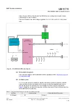
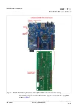
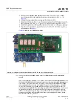
The circuit is supplied with 5V from Arduino port through J1 and J3. Pin no. 5 of J1 is 5V
power supply, while pin no. 6, 7 of J1, and pin no. 7 of J3 represents the power supply
return (ground).
UM11711
All information provided in this document is subject to legal disclaimers.
© NXP B.V. 2022. All rights reserved.
User manual
Rev. 1.0 — 19 January 2022
8 / 30