


NXP Semiconductors
UM10300
User Manual OM6290
UM10300_1
© NXP B.V. 2008. All rights reserved.
User manual
Rev. 1.0— 8 August 2008
23 of 30
6. Flash Magic Quick Start
Setting up the OM6290 board is easy and explanations for the board setup are given
here.
In stand-alone mode only a 9V battery is used to provide power to the board and let the
onboard program run. The board is protected against reversed polarisation of the supply
voltage. Alternatively the USB port can be used to provide power. If also firmware needs
to be modified, the OM6290 board requires a serial connection for In-System
Programming and with a PC already present it is then more economical to use a USB
connection for power. Especially with the backlight fully lit battery lifetime is reduced
which is not an issue if power is supplied via USB. Refer to Chapter 9 for technical data.
When the board is first plugged into the USB port of the PC, Windows will ask for a driver
for ‘Philips LPC2148 VCOM’. The host driver that came with the sample software is
under the "PLPU-S2K" directory.
6.1 Connecting with serial ISP
To connect the OM6290 board for serial programming:
•
Set switch S1 to position ‘Program Flash’;
•
Ensure a jumper is on J3 (can move jumper from J5 for programming);
•
Provide power to the board using a standard USB cable. Battery supply will work too,
but since a PC is being used anyway it is recommended to use the option of USB
powering the board;
•
Connect a user supplied 9-pin serial cable from a COM port on the PC to RS1 on the
OM6290 board;
•
Verify the COM connection using FlashMagic. To do this:
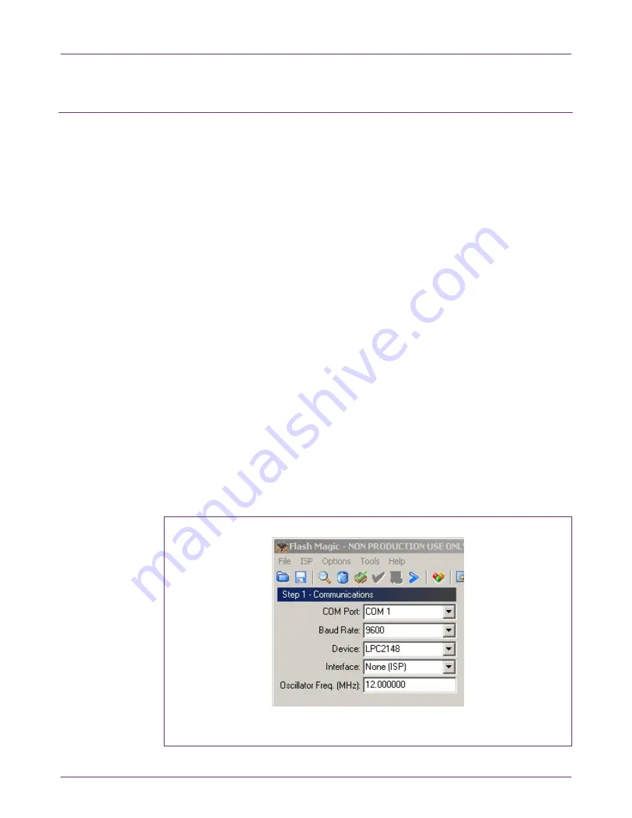
a. Start Flash Magic (using Start – Programs – Flash Magic – Flash Magic) and
configure the COM port interface as indicated below.
Fig 11. Settings for connecting with serial ISP