NXP Semiconductors NTS0304EUK-ARD User Manual Download Page 5

NXP Semiconductors

UM11762

NTS0304EUK-ARD evaluation board

3.2 Assumptions

Familiarity with the SPI and I

2

C bus is helpful but not required.

3.3 Static handling requirements

CAUTION

This device is sensitive to ElectroStatic Discharge (ESD). Therefore care

should be taken during transport and handling. You must use a ground strap

or touch the PC case or other grounded source before unpacking or handling

the hardware.

3.4 Minimum system requirements

This evaluation board requires a Windows PC workstation. Meeting these minimum

specifications should produce great results when working with this evaluation board.

Computer with Windows 10

One USB port (either 3.0 or 2.0 or 1.1 compatible)

One of three EVK boards (MIMXRT1050-EVK, LPC55S69-EVK, 8MMINILPD4-EVK)

along with the associated firmware / GUI software

USB cable for power and data connection between PC and EVK board (if not included

in the EVK package)

4 Getting to know the hardware

4.1 NTS0304EUK-ARD features

Equipped with SPI / I

2

C digital potentiometer for rapid test and measurements

Equipped with programmable power supplies for logic level combination

On-board SPI / I

2

C-bus connector for easy access from external

On-board jumpers for signal isolation of the DUT

Equipped with Arduino Uno R3 port for direct connection with Arduino devices

Fully compliant with IMXRT1050 EVK board, including GUI (Windows 10)

Fully compliant with LPCXpresso55S69 dev. board, including GUI (Windows 10)

Compliant with i.MX Mini LPDDR4 EVK board, including GUI (Windows 10)

Note: For i.MX Mini LPDDR4 EVK Board it is necessary to use IMX8MMINI-IARD

interposer board between the EVK and NTS0304EUK-ARD daughterboard (see

IMX8MMINI-IARD User Manual).

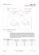
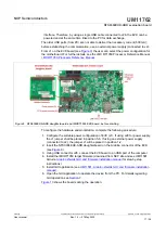
4.2 Kit featured components

Figure 1

 identifies the main components on the board. The main elements are called

out in the picture. The NTS0304E (U6) is placed in the center of the board. The jumper

headers for signal isolation (J8, and J9) are placed near the DUT.
The Arduino port connectors (J1, J4, J5, J6) are located on the bottom side of the board.

UM11762

All information provided in this document is subject to legal disclaimers.

© NXP B.V. 2022. All rights reserved.

User manual

Rev. 1.0 — 27 May 2022

5 / 29

Summary of Contents for NTS0304EUK-ARD

Page 1: ...RD evaluation board is a daughterboard equipped with an Arduino port designated for easy test and design of NTS0304E IC 4 bit dual supply translating transceiver with open drain and auto direction sen...

Page 2: ...D evaluation board Rev Date Description v 1 0 20220527 Initial version Revision history UM11762 All information provided in this document is subject to legal disclaimers NXP B V 2022 All rights reserv...

Page 3: ...heavily depends on proper printed circuit board layout and heat sinking design as well as attention to supply filtering transient suppression and I O signal quality The product provided may not be co...

Page 4: ...al User Interface GUI is provided to facilitate the evaluation of the daughterboard The GUI is used with the following NXP evaluation boards IMXRT1050 EVK Board LPCXpresso55S69 Development Board and i...

Page 5: ...digital potentiometer for rapid test and measurements Equipped with programmable power supplies for logic level combination On board SPI I 2 C bus connector for easy access from external On board jum...

Page 6: ...e NTS0304EUK ARD daughterboard The DUT is the NTS0304E IC U6 The signal lines of the 4 bit level translator the DUT are connected to the circuit through the jumper headers J8 PORT A and J9 PORT B J7 c...

Page 7: ...to J10 analog output connector and to the analog input A0 of the Arduino interface The board contains two programmable LDO voltage regulators LDO1 supplies the VCCA of U7 and U6 and LDO2 supplies VCC...

Page 8: ...MISO_NC_D7 1 D8 MOSI_SDA_D8 2 D9 PWM CLK_SCL_D9 3 D10 SS PWM SPI_CS0_D10 4 D11 MOSI PWM SPI_MOSI_D11 5 D12 MISO SPI_MISO_D12 6 D13 SCK SPI_CLK_D13 7 GND Power supply return 8 AREF Not used 9 A4 SDA N...

Page 9: ...t with the jumper header J7 The OE input of U7 is set HIGH OE active After the level shift the signal lines go from PORT B of the DUT to PORT A of the level translators U8 and U10 through the jumper h...

Page 10: ...led through both SPI and I 2 C bus The bus selection is realized from the input DIS pin 8 of U11 connected to input A2 of the Arduino port The switch U12 disables the digital potentiometer when the lo...

Page 11: ...4 8 SPI I 2 C external connector The SPI I 2 C bus lines can be accessed externally through connector J3 Figure 6 shows the SPI I 2 C EXTERNAL connector J3 is connected to the bus in the section betw...

Page 12: ...ammable power supplies LDO1 and LDO2 Figure 7 depicts the LDO section of the schematic diagram LDO1 provides the power for VCC_LDOUT1 and LDO2 supplies VCC_LDOUT2 power rail Both regulators are contro...

Page 13: ...function of switch position U1 is controlled from the Arduino port through MUX1_LDO1_S0 MUX1_LDO1_S1 MUX1_EN_B pins 1 2 and 5 of Arduino connector J5 The VCC_LDOOUT1 rail feeds the VCCA power pins of...

Page 14: ...rlock circuit was implemented to avoid the above described condition The components involved in the interlock circuit are U1 U2 D3 and D4 The voltage level applied to the enable inputs of the LDOs U3...

Page 15: ...D jumpers continued Figure 8 NTS0304EUK ARD Jumper locations Ref Des Label Description TP1 B1 U6 PORT B TP2 B2 U6 PORT B TP3 A1 U6 PORT A TP4 A2 U6 PORT A TP5 A3 U6 PORT A TP6 B3 U6 PORT B TP7 A4 U6 P...

Page 16: ...tware on PC please download UM11581 Arduino Shields GUI and firmware installation available at https www nxp com docs en user guide UM11581 pdf Once the software is installed the first step is to sele...

Page 17: ...able power configuration of EVK J1 If using J28 for power supply the J1 jumper shall be placed in position 5 6 If using an external power supply connected to J2 the jumper J1 will be placed in positio...

Page 18: ...pment board is equipped with four USB Micro B connectors P5 P6 P9 and P10 The board can be powered through any USB port Using P6 USB connector to connect the board to the PC simplifies the start up op...

Page 19: ...t the development board using port P6 USB port of PC 3 Install the LPCXpresso55S69 target firmware download from NXP site and read the EVK_Firmware_And_GUI_Install_Guide_For_Arduino_Boards pdf instruc...

Page 20: ...erposer board was developed with the role of signal to signal bridge between the 2 x 20 connector pins on the i MX 8M Mini LPDDR4 EVK and the mated connectors of the Arduino port present on the NTS030...

Page 21: ...poser board and i MX 8M Mini LPDDR4 EVK before starting To configure and operate the setup follow the below steps 1 Insert the NTS0304EUK ARD onto the IMX8MMINI IARD interposer board Arduino connector...

Page 22: ...ring that is compliant with IC specifications Use NTS0304E datasheet to read details about internal registers of the DUT IC and data exchange between internal controller and the EVK Assure for correct...

Page 23: ...h EVK appears on the screen Device displays the name of the device under test This GUI supports only NTS0304EUK ARD daughterboard COM port displays port selected for the communication The port is auto...

Page 24: ...the data flow through the chain Set Output Voltage input box allows the user to set the output voltage The voltage should be less than or equal to 2 5 V Protocol drop down list allows the user to sel...

Page 25: ...he data flow direction can be chosen for both sides from Side A to Side B or Side B to Side A by enabling the corresponding checkbox 8 Abbreviations Acronym Description DUT Device Under Test EEPROM El...

Page 26: ...timers SCTimer PWM PLU 16 bit 1 0 Msamples sec ADC Comparator Temperature Sensor AES PUF SHA CRC RNG Product data sheet NXP Semiconductors 6 i MX 8M Mini LPDDR4 EVKB Board Hardware User s Guide User...

Page 27: ...for the customer s applications and products using NXP Semiconductors products in order to avoid a default of the applications and the products or of the application or use by customer s third party...

Page 28: ...15 Fig 9 NTS0304EUK ARD daughterboard and IMXRT1050 EVK board before starting 17 Fig 10 The assembly NTS0304EUK ARD daughterboard IMXRT1050 EVK board operation 18 Fig 11 NTS0304EUK ARD daughterboard...

Page 29: ...4 4 9 3 The interlock 14 4 10 Jumpers and test points 14 5 Installing and configuring software tools 16 6 Configuring the hardware 16 6 1 Using the NTS0304EUK ARD with an IMXRT1050 EVK board 16 6 2 Us...

Reviews: