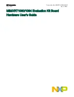
NXP Semiconductors MIMXRT1060 Hardware User'S Manual Download Page 14

J24

J25

D8/CLKO/ICP1

NC

D9/OC1A/PWM

IOREF

D10/SPI_CS

RESET

D11/OC2A/PWM/SPI_MOSI

3.3 V

D12/SPI_MISO

5 V

D13/SPI_CLK

GND

GND

GND

AREF

D14/I2C_SDA

D15/I2C_SCL

2.14 Camera module connector

i.MX RT1060/1064 supports one parallel CSI (Camera Sensor Interface). There is a camera module connector (J35) on the
MIMXRT1060/1064 EVK board. The CA031C based on OV7725 and CA111C based on MT9M114 are used directly.


J35 supports both MT9M114 and OV7725 camera module, but 3.3 V is a violation to MT9M114 spec 3.1 V. It
proved fine for evaluation/demo with 3.3 V supply, but in product design, it is recommended to adjust DCDC output
or add level shifter.

  NOTE  

2.15 User interface switch

There are four user interface switches on the MIMXRT1060/1064 EVK board.

Power switch

ON/OFF button

Reset button

USER button

2.15.1 Power switch

SW1 is a slide switch to control the power of the MIMXRT1060/1064 EVK board when the power supply is from J2.

• Sliding the switch to the ON position connects the 5 V power supply to the evaluation board main power system.
• Sliding the switch to the OFF position immediately removes all power from the board.

2.15.2 ON/OFF button

SW2 is the ON/OFF button for MIMXRT1060/1064 EVK board. A short pressing in OFF mode causes the internal power
management state machine to change state to ON. In ON mode, a short pressing generates an interrupt as a software-controllable
power-down. An approximate 5 seconds or more pressing causes a forced OFF. However, you can disconnect both the boot
mode inputs.

NXP Semiconductors

Specifications

MIMXRT1060/1064 Evaluation Kit Board Hardware User's Guide, Rev. 0, 06/2020

User's Guide

14 / 19

Summary of Contents for MIMXRT1060

Page 1: ...MIMXRT1060 1064 Evaluation Kit Board Hardware User s Guide NXP Semiconductors Document identifier MIMXRT10601064EKBHUG User s Guide Rev 0 06 2020...

Page 2: ...flash 11 2 8 Ethernet connector 12 2 9 USB PHY connector 12 2 10 Audio input output connector 12 2 11 OpenSDA circuit DAP Link 12 2 12 JTAG connector 12 2 13 Arduino expansion port 13 2 14 Camera modu...

Page 3: ...IMXRT1060 1064 EVK board are listed in Table 1 Table 1 Board features Processor NXP Processor MIMXRT1062DVL6A MIMXRT1064DVL6A DRAM Memory SDRAM 256 Mbit 166 MHz IS42S16160J 6BLI DCDC MPS MP2144GJ LDO...

Page 4: ...ort Arduino interface PCB 3 937 inch x 5 9055 inch 10 cm x 15 cm 4 layer board 1 2 MIMXRT1060 1064 EVK contents The MIMXRT1060 1064 EVK contains the following items MIMXRT1060 1064 EVK board USB cable...

Page 5: ...he EVK board The document describes each block shown in Block diagram The document describes each block shown in Figure 1 Figure 1 Block diagram The overview of the MIMXRT1060 EVK board is shown in Fi...

Page 6: ...Figure 2 Overview of the MIMXRT1060 EVK board Front side NXP Semiconductors Specifications MIMXRT1060 1064 Evaluation Kit Board Hardware User s Guide Rev 0 06 2020 User s Guide 6 19...

Page 7: ...ndustrial HMI IoT motor control and home appliances The flexibility of the architecture enables it to be used in a wide variety of other general embedded applications too The i MX RT processor provide...

Page 8: ...ation about MIMXRT1060 EVK boot device selection and configuration see the main board schematic NOTE Table 4 Typical boot mode and boot device settings for RT1064 SW7 1 SW7 2 SW7 3 SW7 4 Boot Device O...

Page 9: ...Q_ON is switched on to enable external DC DC to power up other power domains ON OFF button is used to switch ON OFF PMIC_REQ_ON to control power modes RESET button and WDOG output are used to reset th...

Page 10: ...age VDD_HIGH_IN 3 3 3 3 7 VDD_HIGH_IN supply voltage DCDC_IN 3 3 3 3 6 Power for DCDC VDD_SNVS_IN 2 4 3 3 6 Power for SNVS and RTC USB_OTG1_VBUS USB_OTG2_VBUS 4 4 5 5 5 Power for USB VBUS VDDA_ADC 3 3...

Page 11: ...ch SW7 settings should be ON OFF ON OFF as shown in Typical boot mode and boot device settings 2 6 Hyper flash On the MIMXRT1060 1064 EVK board there is one 512 Mbit hyper flash device To boot from th...

Page 12: ...andard serial and debug adapter It bridges serial and debug communications between a USB host and an embedded target processor CMSIS DAP features a mass storage device MSD bootloader which provides a...

Page 13: ...n definitions of Arduino interface Table 7 Arduino Interface pin definitions J22 J23 UART_RX D0 A0 ADC0 UART_TX D1 A1 ADC1 D2 INT0 A2 ADC2 D3 INT1 PWM OC2B A3 ADC3 D4 T0 XCK A4 ADC4 SDA D5 TI PWM A5 A...

Page 14: ...MIMXRT1060 1064 EVK board Power switch ON OFF button Reset button USER button 2 15 1 Power switch SW1 is a slide switch to control the power of the MIMXRT1060 1064 EVK board when the power supply is...

Page 15: ...is not powered Reset RED LED D21 OpenSDA LED D20 USER LED D18 2 18 LCD interface The enhanced Liquid Crystal Display Interface eLCDIF is a general purpose display controller The eLCDIF block supports...

Page 16: ...PCB stack up information is shown in Table 8 Table 8 Board stack up information Layer Description Copper Oz Dielectric Thickness mil 1 Signal 1 Dielectric 3 2 GND 1 Dielectric 52 3 Power 1 Dielectric...

Page 17: ...es You can download the schematics layout files and gerber files including Silkscreen from nxp com MIMXRT1060 EVK NXP Semiconductors MIMXRT1060 1064 Evaluation Kit Board Hardware User s Guide Rev 0 06...

Page 18: ...EVK board with processor memory interfaces and so on USB cable USB cable Micro B to Standard A Camera CA111C based on MT9M114 Power adapter micro SD card and LCD module are not standard parts of the...

Page 19: ...ment appropriate design and operating safeguards to minimize the risks associated with their applications and products NXP the NXP logo NXP SECURE CONNECTIONS FOR A SMARTER WORLD COOLFLUX EMBRACE GREE...

Reviews: