


Over The Air Programmer Demonstration
MC1322x SMAC Demonstration Application User’s Guide, Rev. 1.3
Freescale Semiconductor
10-11
10.5.2
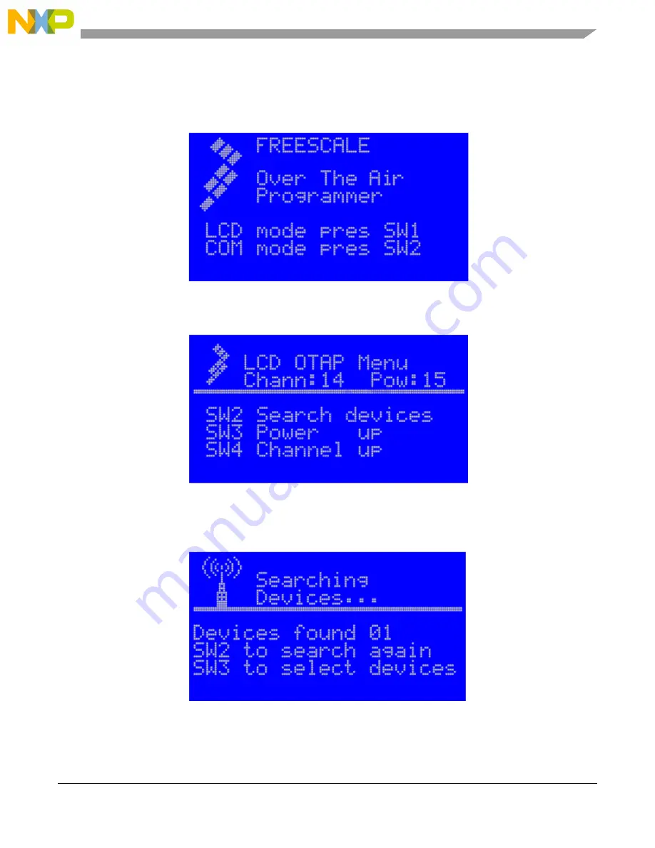
Using The LCD Interface
1. Press the Reset button on the OTAP Programmer Board. The main screen appears as shown in
Figure 10-16
.
Figure 10-16. OTAP Programmer Main LCD Screen
2. Press SW1 on the OTAP Programmer Board. The OTAP menu appears as shown in
Figure 10-17
.
Figure 10-17. LCD OTAP Menu
3. Press SW2 to search for devices to program. The searching devices screen appears as shown in
Figure 10-18
.
Figure 10-18. LCD OTAP Search for Devices