NXP Semiconductors KITUSBSPIEVME User Manual Download Page 7

USB to SPI Interface Evaluation Board, Rev. 1.0

Freescale Semiconductor

7

Modifying and Adding to the Software

To modify and recompile this software, one must download a copy of the CodeWarrior software development suite (IDE) from 
Freescale. The link to this software is:

http://www.freescale.com/CodeWarrior

 The USB to SPI software transfers 8 bytes of data from the SPIGen.exe program, via USB, to the JW32 MCU. The definitions 
of the 8 bytes can be found in the main.c program, and the actual transfer and decoding is done in the USB_driver.c program. 
Comments are provided throughout the code to explain the operation of the individual routines.

Once the code is compiled (without errors), the CodeWarrior IDE provides a means to download the binaries to the P&E Cyclone 
Pro programmer, via the MON08 port to re-Flash the JW32. The documentation for this process is contained in the CodeWarrior 
suite of tools and the P&E documentation.
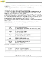
global.h

Some useful defines for debug

jw32_registers.h

More register definitions

main_asm.h

Header file for main_asm.c 

MCHC908JW32FC.H

Header file for MCHC908JW32FC.C

motdef.h

General purpose definitions from the old days

pll.h

Header file for pll.c

spi.h

Header file for spi.c

tb.h

Header file for tb.c Timebase 

timer.h

Header file for timer.c timer initialization

usb.h

Header file for USB_driver.

usb_vars.h

Header for variables used in USB_Driver.c

utilities.h

Header for utilities.

ansii.lib

c library for ansii c functions

Start08.c

Generated by CodeWarrior to define initialization code

Project.prm

Defines interrupt and memory map

Project.map

Map file generated by compile process

Burner.bbl

Some defines used in the programming of the JW32

Summary of Contents for KITUSBSPIEVME

Page 1: ...SBSPIEVME Evaluation Board is a working hardware software example that allows a user to become familiar with the MCHC908JW32FC by means of an actual useful application a USB to SPI and USB to parallel...

Page 2: ...is included on the accompanying CD LED Display The LED s are provided as a visual output device for debugging and test purposes As configured from the factory LED 2 indicates when power is applied and...

Page 3: ...pin outs for the SPI signals and Control and Data signals by using shorting jumper plugs or wire jumpers Consult the specific Freescale Evaluation Board documentation for the correct signal pin defin...

Page 4: ...d JP1 and JP2 are provided to allow the selection of power and clock source for the Evaluation Board JP1 selects the source of the VCC power 5 volts in accordance with the following table Pin Number N...

Page 5: ...acitors C2 and C3 27 pf and resistor R4 10M provide the operating clock source for the JW32 The 4 000 MHz clock is used as a reference for the PLL in the JW32 The internal bus frequency is 8 MHz and t...

Page 6: ...ces of software were licensed from Thesycon a software development company in Germany All of the source code that is available is provided on the Installation CD in a directory called source For an ex...

Page 7: ...ries to the P E Cyclone Pro programmer via the MON08 port to re Flash the JW32 The documentation for this process is contained in the CodeWarrior suite of tools and the P E documentation global h Some...

Page 8: ...y of its products for any particular purpose nor does Freescale Semiconductor assume any liability arising out of the application or use of any product or circuit and specifically disclaims any and al...

Reviews: