


TWRMCF51JGUM
TWR-MCF51JG Tower Module User's Manual
Page 8 of 21
Integrated USB 2.0 Full-Speed Device/Host/OTG Controller supporting connection via USB and
battery charging
Serial audio interface (SAI) providing a direct interface to codecs and to Inter-IC Sound (I2S)
audio devices
Real-time debug support, with six hardware breakpoints that can be configured to halt the
processor or generate debug interrupt
Multi-purpose clock generator with PLL and FLL operation modes; multiple input oscillator or
resonator frequency ranges; two internal trimmable references
SPI, I
2
C, UART (SCI)
GPIO with pin interrupt support, DMA request capability, digital glitch filtering
2.2
Clocking
The C MCUs start up from an internal digitally controlled oscillator (DCO). Software can enable
the main external oscillator (EXTAL/XTAL) if desired. The external oscillator/resonator for the
Multipurpose Clock Generator (MCG) module can range from 32.768 KHz up to a 32 MHz.
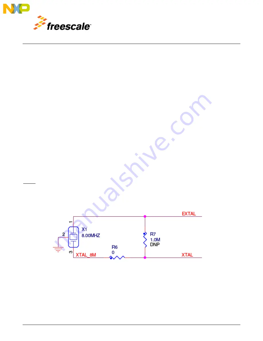
The TWR-MCF51JG provides an 8 MHz ceramic resonator as shown in Figure 4 below and sheet 4 of the
schematics. This oscillator can be used as a clock source for the phase locked loop (PLL) inside the
MCG.
Notes
1.
When R7 is not populated (default), configure the crystal oscillator for low-power operation
(MCG_C2[HGO] = 0).
2.
The resonator used here has internal load capacitors. Therefore no external or internal load
capacitance within the MCU is required.
Figure 4.
Main Oscillator Input
Additionally, the TWR-MCF51JG provides a 32.768 KHz oscillator for an accurate real time clock source.