


System Overview
MC13192EVB Reference Manual, Rev. 1.2
Freescale Semiconductor
2-5
2.7
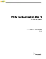
Schematic and Bill of Materials (BOM)
This section contains the 13192-EVB schematic and BOM.
Figure 2-1. Schematic
5
5
4
4
3
3
2
2
1
1
D
D
C
C
B
B
A
A
SS
MOSI
IRQ
100_Ohm2
100_Ohm1
100_Ohm3
100_Ohm4
SPICLK
AntCtrl
MISO
RSTB
RXTXEN
GPIO1
GPIO2
GPIO2
50_Ohm6
DATA+
DATA-
RTS
Rx
CTS
Tx
ATTNB
50_Ohm4
50_Ohm2
CLKO
50_Ohm5
50_Ohm1
AntCtrl
50_Ohm7
50_Ohm3
GPIO1
VDDA
VDDA
3V0_BB
3V0_RF
3V0_BB
3V0_SW
3V0
V_USB
V_RS232
3V0
3V0_BB
3V0
3V0
3V0
3V0
VCC_LNA
VCC_LNA
3V0_LNA
3V0_LNA
V_USB
5V0
3V0
V_RS232
3V0_LNA
3V0_SW
3V0_RF
3V0_BB
V_USB
V_USB
V_USB
V_USB
3V0_SW
GPIO1
GPIO2
AntCtrl
GPIO1
GPIO2
LNACtrl
AntCtrl
LNACtrl
Title
Size
Document Number
Rev
Date:
Sheet
of
© Freescale Semiconductor
80000528000_R0204.DSN
R02.04
ZigBee Evaluation Kit (DIG528-2): Main Schematic
2100 East Elliot Drive
Tempe, AZ, USA
A2
11
Friday, May 05, 2006
JJ/ALA/HBR
2006
www.freescale.com
Title
Size
Document Number
Rev
Date:
Sheet
of
© Freescale Semiconductor
80000528000_R0204.DSN
R02.04
ZigBee Evaluation Kit (DIG528-2): Main Schematic
2100 East Elliot Drive
Tempe, AZ, USA
A2
11
Friday, May 05, 2006
JJ/ALA/HBR
2006
www.freescale.com
Title
Size
Document Number
Rev
Date:
Sheet
of
© Freescale Semiconductor
80000528000_R0204.DSN
R02.04
ZigBee Evaluation Kit (DIG528-2): Main Schematic
2100 East Elliot Drive
Tempe, AZ, USA
A2
11
Friday, May 05, 2006
JJ/ALA/HBR
2006
www.freescale.com
LED3
LED2
LED1
LED4
BDM PORT
SW5
RESET Switch
SW3
SW4
SW1
SW2
Powered by
5VDC < > USB
Correct pin descriptions on IC103, pins 1 and 2
(pin 1 from OUT2 to OUT1, pin 3 from OUT1 to OUT2)
R02.04
Revision history:
2
3
1
J105
DC
J105
DC
R114
27R
R114
27R
C126
Not Mounted
15pF
C126
Not Mounted
15pF
S101
Switch SPST SMD
S101
Switch SPST SMD
C128
10pF
Not Mounted
C128
10pF
Not Mounted
Q103
MMBT3906
Not Mounted
Q103
MMBT3906
Not Mounted
R136
2.2K
Not Mounted
R136
2.2K
Not Mounted
L102
8.2nH
L102
8.2nH
R112
82K
R112
82K
1
2
3
4
5
6
J101
2*3p
J101
2*3p
D102
Red LED
D102
Red LED
PCB101
DIG528-2
PCB101
DIG528-2
R121
27R
R121
27R
R124
0R
Not Mounted
R124
0R
Not Mounted
5
1
6
2
3
4
Z102
LDB212G4020C-001
Z102
LDB212G4020C-001
R101
220R
R101
220R
TP106TP106
TP102TP102
TP104TP104
C125
100nF
C125
100nF
R135
220R
R135
220R
ANT101
F_Antenna
ANT101
F_Antenna
TP105TP105
C120
100nF
C120
100nF
C114
10pF
C114
10pF
R138
0R
R138
0R
C119
100nF
C119
100nF
C105
1.0pF
C105
1.0pF
3V3OUT
6
USBDM
8
USBDP
7
RSTOUT
5
RESET
4
XTIN
27
XTOUT
28
EECS
32
EESK
1
EEDATA
2
TEST
31
TXD
25
RXD
24
RTS
23
CTS
22
DTR
21
DSR
20
DCD
19
RI
18
TXDEN
16
TXLED
12
RXLED
11
PWRCTL
14
PWREN
15
SLEEP
10
AVCC
30
VCC
3
VCC
26
VCC_IO
13
AGND
29
GND
9
GND
17
IC105
FT232BM
IC105
FT232BM
C121
100nF
C121
100nF
D104
Red LED
D104
Red LED
C112
0.5pF
C112
0.5pF
R105
47K
Not Mounted
R105
47K
Not Mounted
D105
Green LED
D105
Green LED
C124
33nF
C124
33nF
CS
1
CLK
2
DI
3
DO
4
GND
5
NA
7
VCC
8
NA
6
IC107
93LC46B
Not Mounted
IC107
93LC46B
Not Mounted
BARCODE101
Label 26*13mm Test BarCode
BARCODE101
Label 26*13mm Test BarCode
A102
Secundary fiducial point (Compside)
A102
Secundary fiducial point (Compside)
C131
10nF
C131
10nF
R119
47K
Not Mounted
R119
47K
Not Mounted
2
4
1,3
Q101
MBC13900
Q101
MBC13900
C101
100nF
C101
100nF
R123
470R
R123
470R
L105
1.5nH
L105
1.5nH
IRQ
12
PTA0/KBIP0
35
PTA1/KBIP1
36
PTA2/KBIP2
37
PTA3/KBIP3
38
PTA4/KBIP4
39
PTA5/KBIP5
40
PTA6/KBIP6
41
PTA7/KBIP7
42
PTB0/AD0
25
PTB1/AD1
26
PTB2/AD2
27
PTB3/AD3
28
PTB4/AD4
29
PTB5/AD5
30
PTB6/AD6
31
PTB7/AD7
32
PTC0/TxD2
2
PTC1/RxD2
3
PTC2/SDA
4
PTC3/SCL
5
PTC4
6
PTC5
7
PTC6
8
PTD0/TPM1CH0
20
PTD1/TPM1CH1
21
PTD3/TPM2CH0
23
PTD4/TPM2CH1
24
PTE0/TxD1
10
PTE1/RxD1
11
PTE2/SS
13
PTE3/MISO
14
PTE4/MOSI
15
PTE5/SPSCK
16
PTG0/BKGD/MS
45
PTG1/XTAL
46
PTG2/EXTAL
47
RESET
1
VDD
19
VDDAD
43
VREFH
33
VREFL
34
VSS1
17
VSSAD
44
PTC7
9
VSS2
18
PTD2/TPM1CH2
22
PTG3
48
EP
49
IC101
MC9S08GT60
IC101
MC9S08GT60
HOLE104
np hole ø4.2mm
HOLE104
np hole ø4.2mm
C111
1µ
F
C111
1µ
F
5
1
6
2
3
4
Z101
LDB212G4020C-001
Z101
LDB212G4020C-001
C116
1µ
F
C116
1µ
F
R115
0R
R115
0R
R122
1.5K
R122
1.5K
R107
470K
Not Mounted
R107
470K
Not Mounted
C1+
2
C1-
4
C2+
5
C2-
6
T1IN
13
T2IN
12
R1OUT
15
R2OUT
10
VCC
19
V+
3
V-
7
GND
18
T1OUT
17
T2OUT
8
R1IN
16
R2IN
9
FORCEON
14
FORCEOFF
20
READY
1
INVALID
11
IC104
MAX3318E
IC104
MAX3318E
D103
Red LED
D103
Red LED
R113
0R
R113
0R
R120
27R
R120
27R
VDD
6
IN
5
VCONT
4
OUT1
1
OUT2
3
GND
2
IC103
µPG 2012TKE-2
IC103
µPG 2012TKE-2
C130
10pF
C130
10pF
C108
6.8pF
C108
6.8pF
1
2
J106
2p
Not Mounted
J106
2p
Not Mounted
R106
470K
Not Mounted
R106
470K
Not Mounted
C102
10pF
C102
10pF
R102
220R
R102
220R
C113
10µ
F
C113
10µ
F
C132
100pF
C132
100pF
C103
10pF
C103
10pF
IN
1
OUT
5
ON/OFF
3
GND
2
NC
4
IC106
LP2981IM5-3.0
IC106
LP2981IM5-3.0
R137
10K
Not Mounted
R137
10K
Not Mounted
C127
Not Mounted
15pF
C127
Not Mounted
15pF
A103
Secundary fiducial point (Soldside)
A103
Secundary fiducial point (Soldside)
HOLE103
np hole ø4.2mm
HOLE103
np hole ø4.2mm
S104
Switch SPST SMD
S104
Switch SPST SMD
C110
100nF
C110
100nF
R110
0R
R110
0R
1
2
3
X102
6.00MHz
X102
6.00MHz
C129
100nF
C129
100nF
ATTNBi
14
CEBi
19
CLKOo
15
GPIO1
11
GPIO2
10
GPIO3
9
GPIO4
8
GPIO7
25
GPIO5
23
GPIO6
24
IRQBo
20
MISOo
18
MOSIi
17
PAO_M
6
PAO_P
5
RIN_M
1
RIN_P
2
RSTBi
12
RXTXENi
13
SM
7
SPICLKi
16
TINJ_M
4
TINJ_P
3
XTAL1
26
XTAL2
27
VBATT
31
VDDA
32
VDDD
21
VDDINT
22
VDDLO1
29
VDDLO2
28
VDDVCO
30
GND
33
IC102
MC13192
IC102
MC13192
1
2
3
4
5
6
7
8
9
10
J107
10p
J107
10p
TP101TP101
R140
220R
R140
220R
S105
Switch SPST SMD
S105
Switch SPST SMD
L101
6.8nH
L101
6.8nH
5
9
4
8
3
7
2
6
1
m1
m2
J103
9p Female Ang
J103
9p Female Ang
D101
Red LED
D101
Red LED
R111
0R
R111
0R
C133
100nF
C133
100nF
R117
470K
R117
470K
A101
Primus datum point (Compside)
A101
Primus datum point (Compside)
L104
5.6nH
L104
5.6nH
1
2
5
3
4
J104
SMA Receptacle, Female
J104
SMA Receptacle, Female
HOLE102
np hole ø4.2mm
HOLE102
np hole ø4.2mm
1
2
3
S106
Switch
S106
Switch
VUSB
1
DATA-
2
DATA+
3
GROUND
4
SHIELD
5
SHIELD
6
J102
USB Serie-B Right Ang.
J102
USB Serie-B Right Ang.
TP108TP108
TP103TP103
C106
100nF
C106
100nF
R116
0R
R116
0R
C122
100nF
C122
100nF
C134
10pF
Not Mounted
C134
10pF
Not Mounted
R103
220R
R103
220R
R126
0R
R126
0R
Q102
MMBT3904
Not Mounted
Q102
MMBT3904
Not Mounted
R118
0R
Not Mounted
R118
0R
Not Mounted
S102
Switch SPST SMD
S102
Switch SPST SMD
S103
Switch SPST SMD
S103
Switch SPST SMD
C115
10pF
C115
10pF
C104
10pF
C104
10pF
C118
100nF
C118
100nF
X101
16.000MHz
X101
16.000MHz
R104
220R
R104
220R
L103
8.2nH
L103
8.2nH
C117
1µ
F
C117
1µ
F
HOLE101
np hole ø4.2mm
HOLE101
np hole ø4.2mm
R108
150R
R108
150R
C109
100nF
C109
100nF
R109
220R
Not Mounted
R109
220R
Not Mounted
C123
1µ
F
C123
1µ
F
TP107TP107
C107
6.8pF
C107
6.8pF
Summary of Contents for FREESCALE MC13192
Page 1: ...Document Number MC13192EVBRM Rev 1 2 09 2006 MC13192 Evaluation Board Reference Manual...
Page 8: ...MC13192EVB Reference Manual Rev 1 2 vi Freescale Semiconductor...
Page 10: ...Safety Information MC13192EVB Reference Manual Rev 1 2 1 2 Freescale Semiconductor...
Page 18: ...System Overview MC13192EVB Reference Manual Rev 1 2 2 8 Freescale Semiconductor...
Page 32: ...RF Front End MC13192EVB Reference Manual Rev 1 2 3 14 Freescale Semiconductor...
Page 34: ...PCB and MC13192EVB Interfaces MC13192EVB Reference Manual Rev 1 2 4 2 Freescale Semiconductor...