


Receiver Firmware
USB Report
DRM050 — Rev 0
Designer Reference Manual
MOTOROLA
Receiver Firmware
41
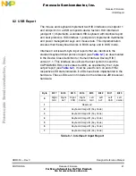
8.2 USB Report
The mouse and keyboard implement two HID interfaces on endpoint 1
and endpoint 2 in a USB composite-device fashion. HID interface 0
(endpoint 1) implements a standard HID keyboard with identical report
and boot protocols. HID interface 1 (endpoint 2) implements multimedia
and power management keys and mouse data. This implementation
ensures that the keyboard works in BIOS setup and in DOS mode.
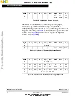
Interface 0 will issue 8-byte input reports that are identical to the
standard keyboard boot protocol report (see
Table 8-1
) as documented
in the Device Class Definition for Human Interface Device (HID)
version 1.1. This interface also allows the host system to send the
CAP/NUM/SCROLL lock status to JB16, as specified by the 1-byte
output report (see
Table 8-2
). It can be used to turn on and off the
respective LED state indicators if LEDs have been implemented in the
hardware. These LEDs are not included in the reference JB16 receiver
hardware.
Byte
Bit 7
Bit 6
Bit 5
Bit 4
Bit 3
Bit 2
Bit 1
Bit 0
0
Right
GUI
Right
ALT
Right
Shift
Right
Control
Left
GUI
Left
ALT
Left
Shift
Left
Control
1
Reserved
2
Keyboard Usage ID (Key Code)
3
Keyboard Usage ID (Key Code)
4
Keyboard Usage ID (Key Code)
5
Keyboard Usage ID (Key Code)
6
Keyboard Usage ID (Key Code)
7
Keyboard Usage ID (Key Code)
Table 8-1. Interface 0 Input Report
F
re
e
sc
a
le
S
e
m
ic
o
n
d
u
c
to
r,
I
Freescale Semiconductor, Inc.
For More Information On This Product,
Go to: www.freescale.com
n
c
.
..