background image

CPCI System Subrack 3 U

Installation

24579-031

www.schroff.biz

8

R1.1, December 16, 2010

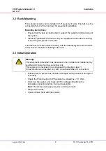
3.2  Rack-Mounting

This subrack system can be installed in 19“ equipment racks. The rack must be 
accessible from the front and rear for equipment installation.

Mounting Instructions:

Ensure that the rack is constructed to support the weight and dimensions of 
the system.

Install any stabilizers that came with your equipment rack before mounting 
or servicing the system in the rack.

Load the rack from the bottom to the top, with the heaviest system at the bottom, 
avoid uneven mechanical loading of the rack.

3.3  Initial Operation

Ensure that the system has not been damaged during transport, storage or 
assembly.

Check the Protective Earth (PE) resistance, should be < 0,1 Ohm.

Switch on the system and check all CPCI voltages directly on the
backplane connectors before the board assembly.

Note:

 The ATX power supply requires a minimum load!

Plug-in the boards

Cover all open Slots with filler panels.

Warning!

This equipment is intended to be accessed, to be  installed and maintained by 
qualified and trained service personnel only.
This eqipment is designed in accordance with protection class 1!
It must therefore be operated only with protective GND/earth connection!

Summary of Contents for CPCI

Page 1: ...CPCI System Subrack 3 U User s Manual Product No 24579 031 December 16 2010 Doc No 63972 255_R1 1...

Page 2: ...ISO 9001 2000 The company cannot accept any liability for errors or misprints The company reserves the right to amendments of technical specifications due to further development and improvement of pro...

Page 3: ...ions 3 2 2 System Overview 3 2 3 Subrack 4 2 4 CPCI Backplane 4 2 5 Power Supply 5 2 5 1 ATX Power Supply 5 2 5 2 Grounding Earthing 5 2 6 Cooling 6 3 Installation 7 3 1 General Installation Guideline...

Page 4: ...CPCI System Subrack 3 U 24579 031 www schroff biz II R1 0 December 16 2010...

Page 5: ...and alone functionality additional elements are required An operational system is achieved only by way of appropriate CPCI boards The completion and final testing of the units have been carried out or...

Page 6: ...ons to avoid accidents before starting to work with parts that carry dangerous voltages Caution This is the user caution symbol It indicates a condition where damage of the equipment or injury of the...

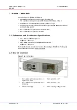
Page 7: ...older for an optional slim line DVD drive Drive holder for an optional 3 5 HDD 2 1 References and Architecture Specifications User Manual CPCI Backplanes Order no 73972 101 User Guide Schroff CPCI Bac...

Page 8: ...des CompactPCI bus 32 bit PICMG2 0 R 3 0 with System Slot right System slot expandable from 4 HP to 8 HP Rear I O on P2 V I O 5 V adjustable to 3 3 V Bridge connector for secondary Backplane Applicabl...

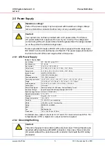
Page 9: ...oltage 90 264 VAC active PFC Input frequency 47 63 Hz Input current 5 A 115 V 2 5 A 230 V Output max 5 V 35 A 3 3 V 28 A 12 V 22 A 12 V 0 8 A Output min 5 V 0 5 A 3 3 V 0 A 12 V 0 5 A 12 V 0 0 A Inrus...

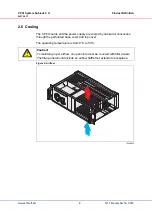
Page 10: ...ower supply are cooled by natural air convection through the perforated base cover and top cover The operating temperature is from 0 C to 50 C Figure 2 Airflow Caution To maintain proper airflow all o...

Page 11: ...amage is present report to the shipper and analyze the damage 3 1 2 Ensuring Proper Airflow Maintain ambient airflow to ensure normal operation If the airflow is blocked or restricted or if the intake...

Page 12: ...iest system at the bottom avoid uneven mechanical loading of the rack 3 3 Initial Operation Ensure that the system has not been damaged during transport storage or assembly Check the Protective Earth...

Page 13: ...ns and therefore a CE marking is not required However when CPCI cards are assembled according to specification the systems fulfill the requirements in accordance with EMC Directive 2004 108 EG and Low...

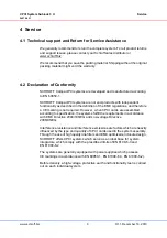
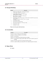
Page 14: ...nnector and mains line switch 4 voltages 3 3 V 28 A 5 V 35 A 12 V 22 A 12 V 0 8 A 1 Complete AC DC cabling 1 Drive holder for a slim line DVD drive 1 Drive holder with front panel 3 U 4 HP for a 3 5 H...

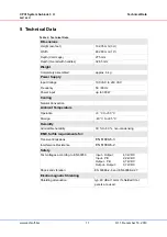
Page 15: ...60 Hz Power input up to 300 W Cooling Natural Convection Ambient Temperature Operation 0 C to 50 C Storage 40 C to 85 C Humidity Admissible humidity 30 to 80 non condensing EMC fulfils requirements fo...

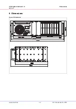
Page 16: ...CPCI System Subrack 3 U Dimensions 24579 031 www schroff biz 12 R1 1 December 16 2010 6 Dimensions Figure 3 Dimensions...

Page 17: ......

Page 18: ...SCHROFF GMBH www schroff biz Langenalberstr 96 100 Tel 49 0 7082 794 0 Fax 49 0 7082 794 200 D 75334 Straubenhardt...

Reviews: