H
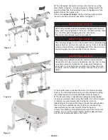
The calf support assembly is simply slide into the mounting
block (Refer to figure 3), and be adjusted by sliding it within the
mounting block than then pushing it down to engage one of the
bottom slots on the square tube.
I
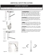
Place the
connector bridge
into the matching holes on both
the roll-in section and tub section (Refer to Figure 3).
SAFETY PRECAUTION!
Both backrest posts must be completely engaged with the seat
frame and securely tightened. If they are not fitted correctly, there
is a risk of the posts dislodging from the seat frame.
This could cause serious injury or even death!
SAFETY PRECAUTION!
The swing-away footrests should be installed into the footrest
clamps after the user has been transferred into the chair. Putting
an extreme amount of weight on the swing-away footrests or
using them as an assistive device when transferring can cause
the entire chair to tip forward, resulting in serious injury or even
death!
SAFETY PRECAUTION!
The connector bridge must be fully seated into the corresponding
holes of both the roll-in section and tub section. If this is not done
correctly, the seat frame could dislodge itself from the chair when
transferring from the roll-in section to the tub section.
- PAGE 2 -
Figure 5
J
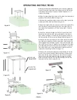
The shuttle frame is released from the roll-in base by pulling
back on the underside release lever and simultaneously sliding
the shuttle towards the tub section base (Refer to Figure 4).
K
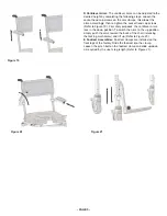
The tilt mechanism is operated by pulling the spring loaded
crank lever outwards and rotating the handle. Once the tilt angle
is reached, we recommend either having the unit at its
highest/largest tilt angle or flat, slowly release the spring loaded
lever and it will automatically lock itself its pin into one of the
indexing holes on the indexing disk (Refer to Figure 4)
L
Index the handle by first positioning the seat in the horizontal
position. The end of the crank handle should be approximately
over the flat head socket bolt on the frame.
Figure 3
Figure 4
H
I
J
K
L


