background image

nuaire.co.uk 

029 2085 8200

BOXER BPS 

ECOSMART CONNECT CONTROL (CO)

Description

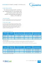
Controller Terminal No Din Rail Terminal No

DI

AI

Relay  

Output

AO (0-10v)

Fresh Air Sensor

IN1

1

Supply Air Sensor

IN2

1

Return/Room Air Sensor

IN3

30,31

1

Input 4 (Pressure Sensor)

IN4

1

Input 5

IN5

36,37

1

Alarm Circuit 1 (Fan, Heater)

IN6

32,33

1

Alarm Circuit 2 (Pump, Filter, 
Thermal Wheel, IO Damper)

IN7

34,35

1

Enable Input Signal

IN8

38,39

1

Configurable Input Signal 
(SL2)

IN9

40,41

1

Extract Fan 0-10V

OUT1

1

Supply Fan 0-10V

OUT2

1

Heat Demand 0-10V

OUT3

1

Cool/Reverse-Cycle Demand 
0-10V

OUT4

1

HX BYpass Relay

OUT5

1

Fault Relay (De-energise on 
fault)

OUT6

1

Fan Run Relay

OUT7

1

Cool/Reverse-Cycle Demand 
Relay

OUT8

1

Recirculation Damper Relay

OUT9

1

230V Enable Input

10

230V Configurable Input

11

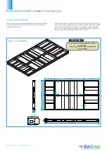
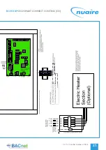
7.8 Connection Chart

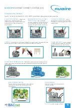
Note that the volt free contacts are not fused. If these are used to power 
any external equipment, the installer must provide adequate fusing or other 
protections.
These contacts are rated at 3A resistive, 0.5A inductive.

Fault connections

 - No fault = the relay is powered.

Fault 

= the relay is unpowered.

Heat demand

 - the relay is powered when heating is selected.

Cool demand

 - the relay is powered when cooling is selected.

A fan start delay can be imposed to allow the damper time to open. This is 
adjustable via display screens or commissioning tools. 

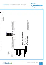
If an I/O damper is fitted, it must be wired to the fan run relay, and the relay 
supplied with the relevant supply voltage.

If required the damper end point relay can be connected in series with alarm 
circuit 2 to monitor for damper faults. The multi-state value ‘IO Damper Fitted’ 
must be set to yes. This will allow the system to ignore alarm circuit 2 if the fans 
are not running and dampers are closed. 

See I/O Damper connection diagram for details.

Switch Live (SL) terminal - A signal of 100-230V a.c. will activate the switched 
live signal.
Switch Live 2 (SL2) terminal - A signal of 100-230V a.c. will activate the 
switched live 2 (Fan Boost) signal.
Note that a signal from an isolating transformer will produce an unpredictable 
result and is not recommended.
Extra low voltage versions of the switched live signals are also available. Link two 
contacts to activate the signal.

7.4 Volt Free Contacts

7.6 Volt Free Contacts

7.5 Switched Live

7.7 Network Settings

Default MS/TP Address: 4

BACnet Instance Number: Randomised & 

Unique for each controller (0 to 4,194,304)

Summary of Contents for ecosmart CONNECT BPS

Page 1: ...828 nuaire co uk 029 2085 8200 Horizontal BPS with INSTALLATION MAINTENANCE INSTRUCTIONS Control 2016 ErP COMPLIANT LEAKAGE CLA SS T H E R MAL RID G I N G CLA SS TB1 D EFLECTIO N CL A SS D1 FOR THE CO...

Page 2: ...Reverse Cycle coil is supplied as standard with Mitsubishi Mr Slim Condenser s and inbuilt PAC Control Note control wiring and piping by others thermistor wiring included Installation must be carried...

Page 3: ...ontal PHX Units Frost Coil LPHW 3 B AH FL R BPS size Frost Coil LPHW Right Handed for Horizontal PHX Units B AH FL L BPS size Frost Coil LPHW Left Handed for Horizontal PHX Units Recirculation Module...

Page 4: ...During installation commissioning operation and maintenance of an air handling unit operatives may be exposed to hazards including rotating components refrigerants and high voltage electricity If misu...

Page 5: ...isplayed on the packaging Some of the modules have an uneven weight distribution and this will be indicated by labelling where appropriate Offloading and positioning of the equipment is the responsibi...

Page 6: ...covered fork lifting channels are located across the width of the base frame if the module length is sufficient to allow this For shorter modules the fork lifting points will be along the length of t...

Page 7: ...e 7 Air leakage air blow marks to the unit casings and unacceptable noise levels could result if the correct installation procedures are not employed The equipment must be stored in a dry internal loc...

Page 8: ...be removed prior to operation of the thermal wheel module IMPORTANT If a frost coil is not fitted then appropriate control methods must be taken to prevent the coils filters and other equipment from...

Page 9: ...32 and 42 the pre assembled dampers and terminals are provided with lifting eyes for on site hoisting into position see Figure 11 below Thoroughly inspect the unit after installation is complete The i...

Page 10: ...nit filters may be changed and the fans coils heat exchanger and condensate tray may be inspected and cleaned if necessary 3 The LPHW and Electrical heater settings coil bleed and drain and all other...

Page 11: ...ed Extract Supply Intake Exhaust Model shown is right handed Figure 14 Access for horizontal plate heat exchanger units Right and Left handed EXTRACT SUPPLY INTAKE DISCHARGE Access Shown from top Left...

Page 12: ...se ensure that the condensate hose is connected between modules Care must be taken to ensure a constant fall in gradient is maintained and the hose is kept taught see Figure 15 Access is available in...

Page 13: ...upply contactor Denotes any character These values do NOT include the condenser units which are powered by a separate supply See the table below or condenser manual Single heater models require a sepa...

Page 14: ...Heat demand the relay is powered when heating is selected Cool demand the relay is powered when cooling is selected A fan start delay can be imposed to allow the damper time to open This is adjustabl...

Page 15: ...TERMINAL BLOCKS The earth terminal block green yellow has a direct electrical connection to the DIN rail with the earthing foot earth connection only TERMINATION OF FINE STANDED CONDUCTORS Open the cl...

Page 16: ...Figure 19 Main wiring points for the customer is to the isolators situated on the sides of the units as shown below Note Cable glands for additional ancillary cabling ISOLATOR POSITIONED ON ELECTRIC H...

Page 17: ...ed to reference the required connection and wiring diagrams Example Unit onsite has code B815H ER CO L This indicates a size 15 unit with electric heating and reverse cycle cooling Section 9 4 and 9 1...

Page 18: ...nuaire co uk 029 2085 8200 BOXER BPS ECOSMART CONNECT CONTROL CO 8 2 Basic Connection Diagram BPS Sizes 05 10 15 20 No Condenser Control Figure 20...

Page 19: ...05 11 20 Leaflet Number 671828 BOXER BPS ECOSMART CONNECT CONTROL CO 19...

Page 20: ...nuaire co uk 029 2085 8200 BOXER BPS ECOSMART CONNECT CONTROL CO 8 3 Basic Connection Diagram BPS RC Sizes 05 10 with Mitsubishi Reverse Cycle DX Control Figure 21...

Page 21: ...05 11 20 Leaflet Number 671828 BOXER BPS ECOSMART CONNECT CONTROL CO 21...

Page 22: ...nuaire co uk 029 2085 8200 BOXER BPS ECOSMART CONNECT CONTROL CO 8 4 Basic Connection Diagram BPS RC Sizes 15 20 with Mitsubishi Reverse Cycle DX Control Figure 22...

Page 23: ...28 BOXER BPS ECOSMART CONNECT CONTROL CO 23 F Engineering Projects Project Data Platinum I Ms EcoSmart Connect Drawings Connect Connection Diagrams Connect Connection Diagrams dwg 07 11 2017 09 45 43...

Page 24: ...nuaire co uk 029 2085 8200 BOXER BPS ECOSMART CONNECT CONTROL CO 8 5 1 BPS Internal Wiring Sizes 05 20 No Heating or LPHW Sheet 1 8 5 BPS Internal Wiring Sizes 05 20 No Heating or LPHW Figure 23...

Page 25: ...05 11 20 Leaflet Number 671828 BOXER BPS ECOSMART CONNECT CONTROL CO 25...

Page 26: ...085 8200 BOXER BPS ECOSMART CONNECT CONTROL CO F Engineering Projects Project Data Platinum I Ms EcoSmart Connect Drawings Connect Control Sch 8 5 2 BPS Internal Wiring Sizes 05 20 No Heating or LPHW...

Page 27: ...05 11 20 Leaflet Number 671828 BOXER BPS ECOSMART CONNECT CONTROL CO 27 hematics Connect Control Diagrams dwg 07 11 2017 09 42 47 AutoCAD PDF Smallest File pc3...

Page 28: ...ONTROL CO F Engineering Projects Project Data Platinum I Ms EcoSmart Connect Drawings Connect Control Schematics Connect Control 8 6 BPS Internal Wiring Sizes 05 20 Electric Heating 8 6 1 BPS Internal...

Page 29: ...05 11 20 Leaflet Number 671828 BOXER BPS ECOSMART CONNECT CONTROL CO 29 Diagrams dwg 07 11 2017 09 42 49 AutoCAD PDF Smallest File pc3...

Page 30: ...085 8200 BOXER BPS ECOSMART CONNECT CONTROL CO F Engineering Projects Project Data Platinum I Ms EcoSmart Connect Drawings Connect Control Schema 8 6 2 BPS Internal Wiring Sizes 05 20 Electric Heating...

Page 31: ...05 11 20 Leaflet Number 671828 BOXER BPS ECOSMART CONNECT CONTROL CO 31 atics Connect Control Diagrams dwg 07 11 2017 09 42 51 AutoCAD PDF Smallest File pc3...

Page 32: ...ER BPS ECOSMART CONNECT CONTROL CO 8 7 BPS Internal Wiring Sizes 05 10 No Heating or LPHW with Mitsubishi Reverse Cycle DX 8 7 1 BPS Internal Wiring Sizes 05 10 No Heating or LPHW with Mitsubishi Reve...

Page 33: ...05 11 20 Leaflet Number 671828 BOXER BPS ECOSMART CONNECT CONTROL CO 33...

Page 34: ...NNECT CONTROL CO F Engineering Projects Project Data Platinum I Ms EcoSmart Connect Drawings Connect Control Schematics Connect Control Diag 8 7 2 BPS Internal Wiring Sizes 05 10 No Heating or LPHW wi...

Page 35: ...05 11 20 Leaflet Number 671828 BOXER BPS ECOSMART CONNECT CONTROL CO 35 grams dwg 07 11 2017 09 42 57 AutoCAD PDF Smallest File pc3...

Page 36: ...ject Data Platinum I Ms EcoSmart Connect Drawings Connect Control Schematics Connect Control Di 8 8 BPS Internal Wiring Sizes 15 20 No Heating or LPHW with Mitsubishi Reverse Cycle DX 8 8 1 BPS Intern...

Page 37: ...05 11 20 Leaflet Number 671828 BOXER BPS ECOSMART CONNECT CONTROL CO 37 iagrams dwg 07 11 2017 09 42 58 AutoCAD PDF Smallest File pc3...

Page 38: ...NNECT CONTROL CO F Engineering Projects Project Data Platinum I Ms EcoSmart Connect Drawings Connect Control Schematics Connect Control Diag 8 8 2 BPS Internal Wiring Sizes 15 20 No Heating or LPHW wi...

Page 39: ...05 11 20 Leaflet Number 671828 BOXER BPS ECOSMART CONNECT CONTROL CO 39 grams dwg 07 11 2017 09 43 00 AutoCAD PDF Smallest File pc3...

Page 40: ...oject Data Platinum I Ms EcoSmart Connect Drawings Connect Control Schematics Connect Control Diag 8 9 BPS Internal Wiring Sizes 05 10 Electric Heating with Mitsubishi Reverse Cycle DX 8 9 1 BPS Inter...

Page 41: ...05 11 20 Leaflet Number 671828 BOXER BPS ECOSMART CONNECT CONTROL CO 41 grams dwg 07 11 2017 09 43 05 AutoCAD PDF Smallest File pc3...

Page 42: ...ONNECT CONTROL CO F Engineering Projects Project Data Platinum I Ms EcoSmart Connect Drawings Connect Control Schematics Connect Control Diag 8 9 2 BPS INTERNAL WIRING Sizes 05 10 Electric Heating wit...

Page 43: ...05 11 20 Leaflet Number 671828 BOXER BPS ECOSMART CONNECT CONTROL CO 43 grams dwg 07 11 2017 09 43 07 AutoCAD PDF Smallest File pc3...

Page 44: ...XER BPS ECOSMART CONNECT CONTROL CO 8 10 1 BPS Internal Wiring Sizes 15 20 Electric Heating with Mitsubishi Reverse Cycle DX Sheet 1 8 10 BPS Internal Wiring Sizes 15 20 Electric Heating with Mitsubis...

Page 45: ...05 11 20 Leaflet Number 671828 BOXER BPS ECOSMART CONNECT CONTROL CO 45...

Page 46: ...NNECT CONTROL CO F Engineering Projects Project Data Platinum I Ms EcoSmart Connect Drawings Connect Control Schematics Connect Control Diag 8 10 2 BPS Internal Wiring Sizes 15 20 Electric Heating wit...

Page 47: ...05 11 20 Leaflet Number 671828 BOXER BPS ECOSMART CONNECT CONTROL CO 47 grams dwg 07 11 2017 09 43 10 AutoCAD PDF Smallest File pc3...

Page 48: ...the heater supply contactor The frost coil is fitted with a burst fired controller with integral setpoint air off thermistor air in frost stat thermal cut out and contactor The burst fired controller...

Page 49: ...05 11 20 Leaflet Number 671828 BOXER BPS ECOSMART CONNECT CONTROL CO 49 9 4 Electric Heater Frost Coil Wiring BPS Sizes 05 10 15 20 Figure 36...

Page 50: ...off temperature is set by the end user via the adjustment dial Eg ESCO TDS If no display room modules are fitted the controller setpoint can be adjusted by changing the BACnet Software Setpoint objec...

Page 51: ...ld be connected to ensure that full counter flow exists i e the entering airflow meets the return connection All coils should be connected with the flow at the bottom and the return at the top unless...

Page 52: ...e Function of slide seal Function of transverse seal Condition of casing Condition of wheel Remove dust and fibres with a soft brush or vacuum cleaner Use caution when blowing dirt out with compressed...

Page 53: ...e is modified or removed Nuaire will accept warranty on the hardware unit provided the replacement does not control the unit beyond its specified limits refer to Nuaire testing standards and Applicati...

Page 54: ...Equipment stored on site prior to installation should be protected from the weather and steps taken to prevent ingress of contaminants 4 0 OPERATIONAL LIMITS 4 1 It is important that the specified op...

Page 55: ...05 11 20 Leaflet Number 671828 BOXER BPS ECOSMART CONNECT CONTROL CO 55 NOTES...

Page 56: ...strial Estate Caerphilly CF83 1NA t 44 0 29 2085 8200 f 44 0 29 2085 8222 e info nuaire co uk www nuaire co uk 05 11 20 Leaflet Number 671828 As part of our policy of continuous product development Nu...

Reviews: