


6
05. 09. 13. Leaflet Number 671632
Installation and Maintenance
MRXBOX95B-LP1EH Mechanical Ventilation with Heat Recovery & Summer Bypass
The filters fitted inside the unit are protected with a
plastic film. Prior to commissioning remove the covers
(fig 13), take off the film and replace.
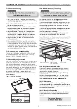
Access to second filter
Filter cover and
filter being removed
Control module
Figure 11. Remove the two filter covers on the underside panel of the
unit, and the filters can be pulled out of the unit using the tab on
the lower edge of the filter.
Isolation - Before commencing work make sure that the unit,
switched live and Nuaire control are electrically isolated
from the mains supply and switched live supply.
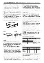
Figure 10. PCB inside enclosure.
Access to Humidistat
adjustment pot
Control module
7.0 Commissioning
1. For the required air flow rates please refer to the design
specification for the property, follow 2.4, or refer to building
regulations ADF 2006/2010.
2. The unit is supplied with independent control for both normal
and boost airflows. (see fig. 10).
3. Correct commissioning is essential to ensure the ventilation
air flowrates are met. It also ensures the unit is not over
ventilating and causing excessive power consumption.
4. Commissioning should be carried out in accordance with
building regulations document “Domestic ventilation
compliance guide”. A calibrated moving vane anemometer
and hood will be required to carry out commissioning.
5. Adjustment valves should be locked in place to prevent
further adjustment.
6. Once commissioned the home owner / tenant should be
informed that the unit should not be adjusted as it will have
a detrimental effect on the indoor air quality and could result
in condensation and mould growth. The label covering the
control has an adhesive panel which should be removed post
commissioning to prevent tampering.
7.1 Summertime boost facility
The unit has to ability to override both the trickle and boost
speeds to operate the fan to maximum airflow. See wiring
diagram for details of operating this facility.
7.2 Humidity adjustment
This product contains an internal humidity sensor fitted into the
airflow extracting from the wet rooms. When the unit senses
that the humidity exceeds the set point the unit will boost to
that set by the commissioned boost speed. The set point can be
found on the bottom of the unit (see fig 10) and is at its least
sensitive when turned fully clockwise. Note that the sensor is
measuring humidity from all the wet rooms at the same time
and should not be relied on to solely boost the unit.
Additional switch should be used local to the wet rooms (see
wiring diagrams).
8.0 Maintenance/Cleaning
We recommend that the two G3 fiters are inspected after
6 months, and replaced every 12 to 18 months.
The filters can be removed from the unit by removing the two
filter covers on the bottom panel of the unit. Take hold of the
two circular tabs either end of the filter covers and pull to
remove. (see fig. 11).
The filter can now be extracted by pulling the removal loop on
the edge of the filter. Once the filters have been inspected
return or replace them as necessary.
Inspect the heat exchanger every 5 years. Generally check
for damage and security of components. Refit cover.
9.0 Replacement of Parts
Should any component need replacing Nuaire keep extensive
stocks for quick delivery. Ensure that the unit is electrically
isolated, before carrying out any work.
Note: The supply cable must be replaced by an electrically
competent person.
When ordering spare parts, please quote the serial number
of the unit and the ARC number of the purchase if possible.
(This information will be available on the fan label).
10.0 Warranty
The 5 year warranty starts from the day of delivery and
includes parts and labour for the first year and parts only for
the remaining 4 years. This warranty is conditional on planned
maintenance being undertaken
.
10.0 Service Enquiries
Nuaire can assist you in all aspects of service. Our Technical
Support department will be happy to provide any assistance
required.
Technical Support
029 2085 8400


