


GENERAL RULES
The installation of an oil burner should
be carried out in accordance with local
regulations. The installer of the burner
must therefore be aware of all
regulations relating to oil and combu-
stion.
Only oil suitable for the burner should
be used and then in combination with
a suitable oil filter before the oil pump
of the burner.
If the burner is replacing an existing
burner make sure that the oil filter is
replaced or cleaned. The installation
must only be undertaken by experien-
ced personnel.
INSTALLATION INSTRUCTIONS
General installation instructions ac-
company the burner and should be
left in a prominent place adjacent to
the burner.
ADJUSTMENT OF BURNER
The burner is from the factory pre-set
to an average value that must then be
adjusted to the boiler in question.
All burner adjustments must be made in
accordance with boiler manufacturers
instructions.These must include the
checking of flue gas temperatures,
average water temperature and CO
2
or
O
2
concentration.
To adjust the combustion device, start
by increasing the air volume somewhat.
When the burner starts it is burning
with excess air and smoke number 0.
Reduce the air volume until soot occurs
and increase again to reach a
combustion free of soot.
By this procedure an optimum adjust-
ment is obtained. If larger nozzles are
used the preadjustment of the air
volume must be increased.
CONDENSATION IN CHIMNEY
A modern burner works with less ex-
cess air and often also with smaller
nozzles than older models. This
increases the efficiency but also the
risk of condensation in the chimney.
The risk increases if the area of the
chimney flue is too large. The tempera-
ture of the flue gases should exceed
60°C measured 0,5 metres from the
chimney top.
Measures to raise the temperature:
Insulate the chimney in cold attics
Install a chimney liner
Install a draught regulator (dilutes the
flue gases during operation and dries
them up during standstill)
MAINTENANCE
The boiler/burner should be exami-
ned regularly for any signs of malfunc-
tion or oil leakage.
GENERAL INSTRUCTIONS
Increase the oil quantity
Raise the flue gas temperature by
removing turbulators, if any, in the
boiler.
INSTRUCTIONS FOR USE
The end user should be instructed
about the operation and safety features
of the burner.
He should also be made aware of the
importance of the area around the
boiler/burner being kept free of com-
bustible material.
PUMP ADJUSTMENT
See separate description.
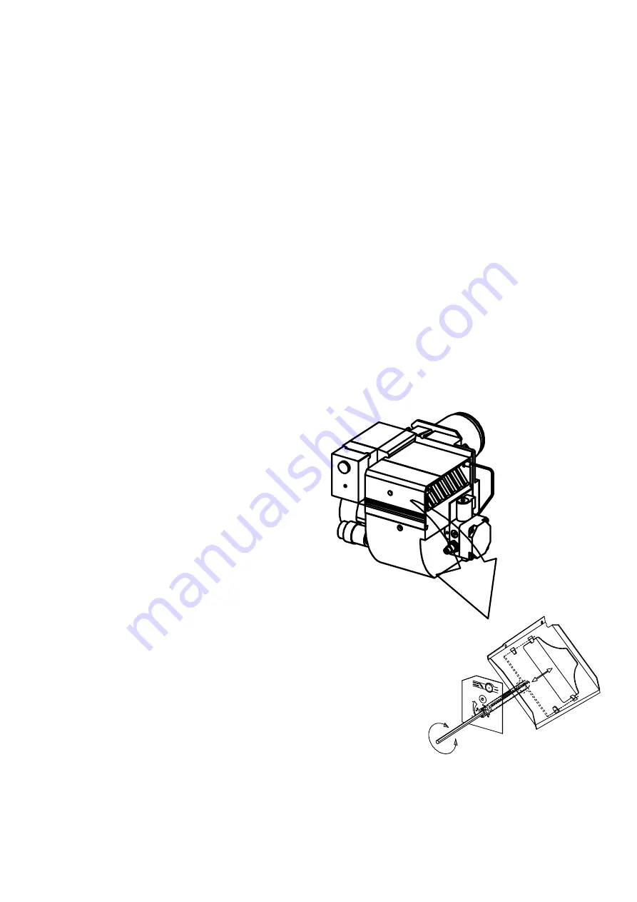
ADJUSTMENT OF BURNER
To obtain a correct adjustment a flue
gas analysis and a temperature
measurement must be carried out.
Otherwise there is a risk that a bad
adjustment may cause a formation of
soot, bad efficiency or condensate in
the chimney.
171 305 67 97-01
AIR ADJUSTMENT 0-32


