


Page 11
NOL Compact Modulating
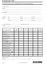
Check that all relevant documentation is
available including, where appropriate:
The agreed plant performance
specifications.
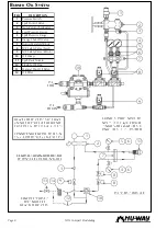
Plant drawings and pipework layouts.
Electrical logic and wiring diagrams.
Certificates confirming satisfactory
completion of procedures such as
soundness testing and electrical safety
tests.
Commissioning, operating and
maintenance instructions for the plant.
Establish that the operation of plant other
that being commissioned will not have an
adverse effect on the operation of the plant
to be commissioned and similarly, that the
operation of the plant to be commissioned
will not have and adverse effect on other
plant.
Confirm that the operation of adjacent plant
and machinery will not constitute a hazard
to the personnel involved in commissioning.
Pre-firing Checks
With the oil and power switched off, carry out the
following checks.
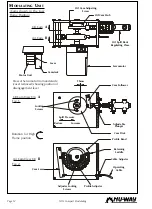
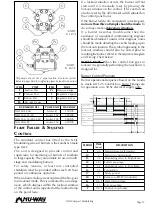
Check the nozzle size and position relative
to the diffuser plate. (The burner head
dimensional details are given on page 20).
Check that the electrode positions and H.T.
leads are correct.
Check the fan motor overload settings.
If the appliance is a boiler, check that the
water level is correct, the controlling valves
are open and that the water pumps are in
working order.
If a flue damper is fitted, check that it is
correctly interlocked to the burner or fixed
in the fully open position.
Ensure that there is a good oil supply to the
burner pump. Bleed one or two gallons from
the flexible to eliminate any pipe scale and
air from the system.
Check that the oil supply is of the
recommended temperature and pressure.
Bleed the burner pump manually by
removing the right hand ¼ BSP plug in the
top of the pump until air free oil flows.
Switch on the electricity supply to the burner.
Remove the access lid on the modulating
cam box unit.
Switch on the burner at the control panel.
The modulating unit camshaft should now
rotate to the high flame setting, and the
combustion air motor will start the air pre
purge phase.
Allow the fan motor to run up to speed,
switch off the burner and check the fan
rotation (Anti clockwise as viewed from the
motor side) as the fan slows down.
Remove and cover the photoelectric cell with
a clean lint free cloth, switch on the burner,
and allow it to run through to lockout.
During this run check that the ignition spark
is occurring, and note the spill and line oil
pressures at the moment of ignition. Reset
the sequence control and repeat the run if
necessary to check these functions. If
necessary, adjust the spill pressure to the
correct figure according to the nozzle
specification and the line pressure at the
burner pump to 27.8 bar (400 psi).
THE BURNER IS NOW READY TO BE
COMMISSIONED.
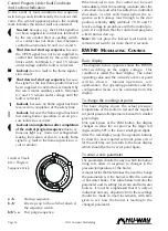
Manual Operation
Check that the RWF40 controller is configured
correctly (refer to page 17). Press and hold the EXIT
key until the manual operation indicator
illuminates. The modulating motor can now be
inched using the increase & reduce buttons on
the controller face. Press and hold the EXIT key
until the manual operation indicator extinguishes
to return to automatic mode
Commissioning the Burner
New burners are generally supplied against the
firing specification of the appliance. In this case the
system and spill pressures may be pre set and
require checking and minor adjustments only. The
following section describes how to set up the
modulating cam box unit from a scratch situation.
The modulating cam layshaft can be rotated by
hand by using the gearbox disengagement lever in
the drive servomotor.
Ensuring that the modulating cam
arrangement is in the low flame position,
adjust the oil cam (see fig. 1 on page 12) so
that it gives approximately 1.5mm throw
(3mm stroke) and lock in position.
Check to ensure that the spill valve push rod
bears lightly against the oil cam.


