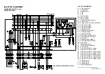
ELECTRIC EQUIPMENT
OIL BURNER CONTROL: LAL1...
WIRING DIAGRAM
LIST OF COMPONENTS
A1
Oil burner control
B1
Photoresistor
F1
Operating fuse
F2
Fuse
F3
Fuse
H1
Lamp, Stage 1
H2
Lamp, Stage 2
H3
Lamp, Stage 3
K1
Thermal overload protection
M1
Burner motor
M2
Damper motor L&S SQN75.436A21B
P1
Time meter, Stage 1
P2
Time meter, Stage 2
P3
Time meter, Stage 3
S1
Operating switch
S2
Operating switch, Stage 2
S3
Control thermostat
S4
Temperature limiter
S5
Micro switch for hinged door
S6
Control thermostat, Stage 2
S7
Main switch
S8
Operating switch, Stage 3
S9
Control thermostat, Stage 3
S20 Main switch
T1
Ignition transformer
X1
Connection terminal board
X2
Earth terminal
X3
Plug-in contact "Euro", burner
X4
Plug-in contact "Euro", boiler
X5
Plug-in contact "Euro", stage 3 burner
X6
Plug-in contact "Euro", stage 3 boiler
X7
Plug-in contact "Euro" 3-phase, burner
X8
Plug-in contact "Euro", 3-phase, boiler
X9
Plug-in contact "Euro", stage 2 burner
X10 Plug-in contact "Euro", stage 2 boiler
Y1
Solenoid valve 1
Y2
Solenoid valve 2
Y3
Solenoid valve 3
Y4
Safety solenoid valve
Mains connection and fuse in accordance with local regulations.
171 425 09 01-01
If S6 is missing connection between L1 and L2.
If S9 is missing connection between T6 and T8.
Damper position
3N ~50/60H
Z
400 V
Summary of Contents for MOL 1650-3R B70 2-3
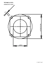
Page 4: ...TECHNICAL DATA DIMENSIONS OF FLANGE 171 225 77 00 01 14 310 324 380 205 5...
Page 14: ......
Page 16: ...NOTES...
Page 17: ...NOTES...


