background image


Rev. December 19, 2008 


Page 19 of 19 

11.


WARRANTIES 


Your 

NU-AIR

 Contractor Edition Heat Recovery Ventilator Transferable Warranty 

For Canada and United States 

Should your 

NU-AIR

 Contractor Edition Heat Recovery Ventilator (HRV) cease to function within two 

(2) years for models CEA15-R, CEA18-C, CEA20-D of the date of original purchase (effective January, 
01, 2007) due to defective material or workmanship of the product, 

NU-AIR

 Ventilation Systems Inc. 

will supply a new or rebuilt part FOB Factory to replace the defective part. Delivery, installation, and 
labour cost would be your responsibility. 
 
Fifteen Year HRV Core Warranty 
 
If  the  aluminum  core  in  your 

NU-AIR

  CEA  Series  Heat  Recovery  Ventilator  fails  due  to  a  defect  in 

material  or  workmanship 

NU-AIR

  Ventilation  Systems  Inc.  will  supply  a  new  core  FOB  Factory  to 

replace the defective part. Delivery and labour costs are your responsibility. 
 

Nu-Air warrants its ERV core to be free from manufacturing defects for a period of one year. 

 
Warranty Limitations 
 
The above warranty does not cover damage to the unit while in  your possession (other than damages 
caused by defective parts or material) due to the following: 1) improper installation or unreasonable use 
of unit: 2) failure to provide reasonable and necessary maintenance. If the unit is put to commercial use 
or application other than residential use, warranty is for a period of one (1) year.  


P.O. Box 2758 Windsor, Nova Scotia Canada B0N 2T0 

Phone: 902 798 2261  Fax: 902 798 2557 

Email: 

[email protected]

 Website: www.nu-airventilation.com
Summary of Contents for CEA15-R

Page 1: ...PE ER RA AT TI IN NG G M MA AI IN NT TA AI IN NI IN NG G I IN NS ST TA AL LL LI IN NG G Y YO OU UR R H HE EA AT T R RE EC CO OV VE ER RY Y V VE EN NT TI IL LA AT TO OR R FOR MODELS CEA15 R CEA18 C AND CEA20 D LEAVE THIS DOCUMENT WITH THE HOMEOWNER Specifications dimensions and ratings may change without notice as a result of ongoing product development and improvements TABLE OF CONTENTS ...

Page 2: ...STAT 1 11 3 4 Windsor Control Part WIN 1 11 3 5 Windsor Timer WIN 20 11 3 6 Spring Wound Timers 12 3 7 Remote On Off Switching 12 3 8 Furnace Interlock 12 4 Arctic Defrost Mode 12 5 START UP 12 6 OPERATING HINTS 13 7 MAINTENANCE 13 7 1 Filters 13 7 2 Fans 13 7 3 Condensate Drain 13 7 4 Core 13 7 5 Exterior Hoods 13 7 6 Grills Duct Work 14 8 ANNUAL SERVICING 14 9 TROUBLE SHOOTING 15 10 ELECTRICAL S...

Page 3: ...dards are met Do not mount the fresh air supply near a source of contaminated air such as automotive exhaust gas or propane exhaust or oil tanks Do not hook a dryer exhaust to an HRV Combustion appliances such as furnaces and hot water heaters must not draw combustion air directly from an HRV Do not connect a range hood to any part of this system Do not install in attics or other unconditioned spa...

Page 4: ...n this system the HRV supply air to the house is introduced into the return duct of the forced air furnace Separate additional ductwork is used to transfer stale air from the wet rooms to the HRV 2 2 2 1 Extended System Continuous Ventilation The furnace fan may not need to run continuously with this system Check local code requirements For improved supply air distribution during continuous ventil...

Page 5: ... Items The HRV comes equipped with Filters Anti Vibration Straps Heat Recovery Core Drain Hose Assembly Connections for timers remote controls furnace interlock 2 2 5 Control Options sold separately Windsor mechanical control WIN 1 Windsor 20 minute timers up to 6 each system WIN 20 2 3 Ducting to The Outside Between the weather hoods and the HRV you must use fully insulated ducting with an integr...

Page 6: ...ent or furnace vent In addition ASHRAE Standard 62 99 recommends the following Ventilation systems should be designed to prevent the reintroduction of exhaust contaminants condensation or freeze ups and growth of microorganisms Make up air inlets and exhaust air outlets shall be located to avoid contamination of the makeup air Contaminants from sources such as cooling towers sanitary vents vehicul...

Page 7: ...esign the duct system 2 7 Drain Connections Access to a drain or sump is required to handle the HRV condensate Care should be taken to run the condensate tube where it cannot freeze For best results Nu Air recommends the following steps be followed when installing drain kits on residential HRV s 1 Apply the O ring supplied to the flange of each drain spout A 2 Insert the drain spouts through the h...

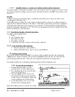
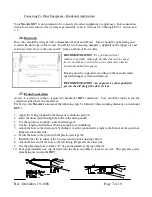
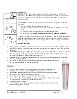
Page 8: ...ts and push the duct back into itself Insert the flow grid and tape the joint between the flow grid and ductwork 2 Set the HRV on high speed Mount the magnehelic gauge level and plumb Join the hoses from the flow grid to the magnehelic gauge The needle of the magnehelic gauge should read positively Switch hose connections if the needle falls below zero 3 Ensure again that the balancing dampers are...

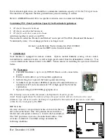
Page 9: ...mer s You can also interlock the furnace blower to the HRV Various means of controlling the system are described below 3 1 Features Powerful transformer up to six 6 WIN 20 Timers can be connected in parallel Field selectable defrost cycle for northern applications Self resetting fuse to protect the board against mis wiring Variable low speed control HRV low speed can be adjusted between a minimum ...

Page 10: ... power failure for instance Self resetting fuse Field mis wiring of timers or dehumidistats may cause the fuse to trip If this happens remove the control wires and allow the fuse to reset This may take a few minutes Check your manual for proper wiring connections Troubleshooting using the PCB light There is a small green light on the board located just below the DIP switches This light will either...

Page 11: ...perate on a low speed for continuous ventilation with intermittent high speed for moisture on air quality control The dehumidistat will switch the HRV to high speed when the relative humidity of the air around it exceeds its set point When the humidity falls below the set point the machine drops out of high speed 3 4 Windsor Control Part WIN 1 The Windsor Dehumidistat Control incorporates a 3 posi...

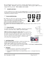
Page 12: ...urnace controls R G lines to HRV terminals labeled R G NOTE For a furnace connected to a cooling system When using the built in furnace interlock relay on the HRV in conjunction with certain older mercury bulb thermostats energizing the R and G terminals will also cause 24 volts to be sent through the Y terminal which will initiate the outdoor condenser If this is the case there are two possible s...

Page 13: ... three months Polyester filters should be replaced annually Permanent electrostatic filters are available from your Nu Air dealer Filters remove easily by opening the front cover 7 2 Fans When cleaning the filters take the opportunity to vacuum any interior surfaces including the fan blades No other service is required as these fans are designed to operate continuously without lubrication 7 3 Cond...

Page 14: ...s Repair any punctures using foil tape 8 ANNUAL SERVICING Your HRV should undergo annual general servicing by an accredited contractor This servicing should include the following a The six maintenance items above b A general check for proper operation Controls and electrical connections should be inspected c Verification that intake and exhaust air flows are properly balanced d Re balancing as nec...

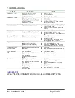
Page 15: ... dampers Check defrost system Note minimal frost build up is expected on cores before unit initiates defrost cycle function Supply air feels cool HRV air flows incorrectly balanced Improper location of supply grills Extremely cold outside temperatures Moving air feels cooler than it actually is Balance HRV Locate grills high on walls or in ceiling If supply air is installed into return line of fur...

Page 16: ...Rev December 19 2008 Page 16 of 19 10 ELECTRICAL SCHEMATICS 10 1 WINDSOR Wall Controls Wiring Diagram WIN 20 WIN 1 ...

Page 17: ...Rev December 19 2008 Page 17 of 19 10 2 24V Standard D Stat Wiring Diagram Part DSTAT 1 NOTE Jumper must be removed if WIN 20 timers are installed ...

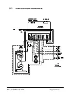
Page 18: ...Rev December 19 2008 Page 18 of 19 10 3 Damper Defrost and Re circulation Defrost ...

Page 19: ...at Recovery Ventilator fails due to a defect in material or workmanship NU AIR Ventilation Systems Inc will supply a new core FOB Factory to replace the defective part Delivery and labour costs are your responsibility Nu Air warrants its ERV core to be free from manufacturing defects for a period of one year Warranty Limitations The above warranty does not cover damage to the unit while in your po...

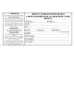
Page 20: ... si pour une raison fortuite nous devoins vous faire parvenir un avis de réparation ou de rappel du produit P PR RO OD DU UC CT T W WA AR RR RA AN NT TY Y R RE EG GI IS ST TR RA AT TI IO ON N C CA AR RT TE E D D I IN NS SC CR RI IP PT TI IO ON N D DE E L LA A G GA AR RA AN NT TI IE E D DE E V VO OT TR RE E P PR RO OD DU UI IT T FIRST NAME LAST NAME NOM DU PRÉNOM ________________________ NOM DE FAM...

Page 21: ...P O Box 2758 Windsor Nova Scotia Canada B0N 2T0 Ph 902 798 2261 Fax 902 798 2557 ...

Reviews: