Rev. December 19, 2008
Page 12 of 19
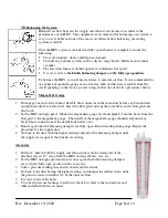
Up to six (6) timers
can be connected in series or parallel. Match terminals on back of switch to
terminals on HRV. "SWITCH", "LED" and "24 V COM (PWR)". When engaged, the HRV will run in
high speed for twenty minutes.
Three-conductor wire is needed.
3.6
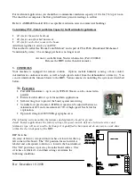
Spring Wound Timers
Connect to "HUM" and "24 V COM" using
two-conductor wire.
To select between continuous low
speed operation or intermittent high speed when no other control is being used, use a jumper wire
connection as described in 3.2 above.
3.7
Remote On/Off Switching
Basic RNC type control can be achieved using a standard light
switch. Add a jumper to 24 V COM and CONT for
continuous low speed. For manually switched high speed,
connect a switch between HUM and 24 V COM.
Remote On/Off Switching With Internal Dehumidistat
For continuous low with automatic humidity control, connect the on/off switch to "CONT" and "24V
COM".
3.8
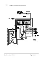
Furnace Interlock
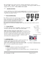
To interlock the furnace blower with the HRV, supply 24 V in and out from
the furnace controls R & G lines to HRV terminals labeled R&G.
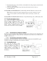
NOTE - For a furnace connected to a cooling system
: When using the built-in
furnace interlock relay on the HRV in conjunction with certain older mercury bulb
thermostats, energizing the R and G terminals will also cause 24 volts to be sent
through the Y terminal which will initiate the outdoor condenser. If this is the case,
there are two possible solutions. Either upgrade the thermostat to a digital type
which does not have Y connected to G internally, or install the isolation
relay as shown in the wiring diagram at right.
4.
Arctic Defrost Mode
A field selectable Arctic Defrost Mode is available on all models and
should be used for temperatures below -20
0
C (-4 F) for fan
shutdown defrost models and areas with temperatures reaching
below -30
0
C (-22
0
F) for damper defrost or recirculation models. Consult
Nu-Air Ventilation Systems
Inc.
or your nearest wholesaler for more information.
5.
START-UP
•
Ensure the controls are connected in accordance with Section 3.
•
For electrical hook-up, plug into a 120 volt receptacle.
•
Ensure that the machine is piped to an adequate drainage source, i.e. through the drain hose
supplied.
IN (R)
OUT (G)
FURNACE INTERLOCK


