


9
j. Power ON each of the slaves connected.
k. Power ON the master switch.
l. Power ON each of the CPUs.
3. CONFIGURATION OF DIP-SWITCHES 1-6
:
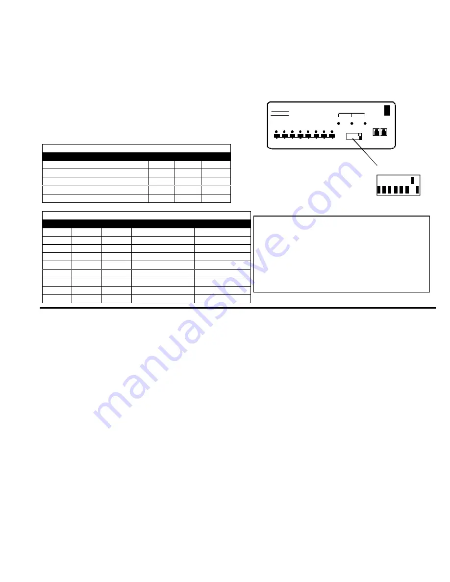
All units are configured using switches 1 thru 6 of the 8-position dip-switch (located on the front of each unit) according to Tables 1
and 2. (Switches 7 and 8 are configured for the keyboard on page 3.)
Front Panel Configuration Switches
Table 1 *
(default settings)
Switch
1
5
6
S T A N D - A L O N E S W I T C H
O F F *
O F F *
O F F *
S L A V E
O N
O F F
O F F
M A S T E R W / 4 - P O R T S L A V E S
O F F
O F F
O N
M A S T E R W / 8 - P O R T S L A V E S
O F F
O N
O F F
M A S T E R W / 1 6 - P O R T S L A V E S
O F F
O N
O N
Table 2 *
(default settings) Master & Slave dip switch 2-4 Settings
2
3
4
M a s t e r w i t h -
Slave Setting
O F F *
O F F *
O F F *
No Slave Attached
N/A
O F F
O F F
O F F
1 Slave attached
Slave Unit #1
O F F
O F F
O N
2 Slaves attached
Slave Unit #2
O F F
O N
O F F
3 Slaves attached
Slave Unit #3
O F F
O N
O N
4 Slaves attached
Slave Unit #4
O N
O F F
O F F
5 Slaves attached
Slave Unit #5
O N
O F F
O N
6 Slaves attached
Slave Unit #6
O N
O N
O F F
7 Slaves attached
Slave Unit #7
O N
O N
O N
8 Slaves attached
Slave Unit #8
U S I N G T H E N T I U N I V E R S A L K V M S W I T C H
Control over the computers attached to the NTI Universal KVM switch is achieved through operation of the Universal KVM switch.
Once the Universal KVM switch is properly connected, the Universal KVM switch will enable a connection to be made between the
c o m p u t e r s a t t a c h e d t o i t s V I D E O - P C - x a n d K E Y - x p o r t s a n d t h e k e y b o a r d , m o n i t o r , a n d m o u s e a t t a c h e d t o t h e M O N I T O R a n d
KEYBD ports. The lights on the control panel of the Universal KVM switch will illuminate depending on which port (and
s u b s e q u e n t a s s o c i a t e d c o m p u t e r ) is being connected to the keyboard, monitor, and mouse. The choice of which computer a
keyboard, monitor, and mouse will be connected to is determined by controlling the Universal KVM switch either through the front
control panel on the Universal KVM switch, by keyboard control, or by optional methods such as Wired Remote Control, RS232,
Infrared, or an On Screen Display. An LCD display can also be added to enable selection and control of computers by name.
F R O N T P A N E L C O N T R O L
There is a touch-switch and LED on the front panel of the Universal KVM switch for each computer the switch will connect
the keyboard, monitor, and mouse to. Pressing any touch-switch on the front panel of the Universal KVM switch will connect the
selected computer to the keyboard, monitor, and mouse.
Holding down any front panel touch-switch for more than 2 seconds will cause the Universal KVM switch to cycle through all
m o d e s o f o p e r a t i o n i n c l u d i n g C O M M A N D , S C A N , B R O A D C A S T , a n d N O R M A L ( d e s c r i b e d o n p a g e s 1 0 a n d 1 1 ) . T h e t h r e e L E D s
on the front panel indicate which mode is selected. Release the touch-switch when the L E D s i n d i c a t e t h e d e s i r e d m o d e . W h e n
n o LEDs are illuminated the user is in Normal Mode controlling directly the computer to which the user is connected through the
Universal KVM switch.
8-POSITION
DIP-SWITCH
About Table 2:
T h e s e s w i t c h s e t t i n g s a r e u s e d b y t h e s l a v e ( s ) t o
establish its identity (i.e. location in the group) to
the master.
I n a m a s t e r , t h e s a m e s w i t c h e s a r e u s e d to
c o n f i g u r e t h e m a s t e r f o r h o w m a n y s l a v e s a r e
attached to it.
ON
OFF
NETWORK
TECHNOLOGIES
INCORPORATED
1 2 3 4 5 6 7 8
ST-8U
NTI
1
2
3
4
5
6
7
8
MODE
SCAN
BROAD
CAST
COM
MAND
REMOTE REMOTE
OUT IN
ON
OFF
1 2 3 4 5 6 7 8
Fig. 17


