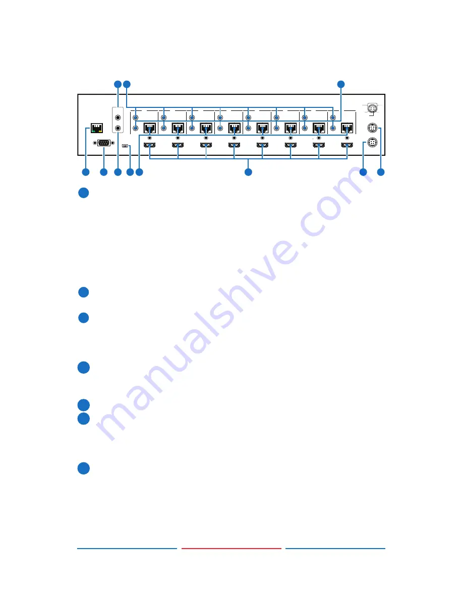
NTI SM-8X8-C6HDR-POE-HDBT Operation Manual Download Page 9

4

6.2 Rear Panel

RS232

SERVICE

IR OUT

IR IN

IR OUT

IR IN

IR OUT

IR IN

ALL

A

B

C

D

E

F

G

H

CAT5e/6 OUT

IR OUT

IR IN

CAT5e/6 OUT

IR OUT

IR IN

CAT5e/6 OUT

IR OUT

IR IN

CAT5e/6 OUT

IR OUT

IR IN

CAT5e/6 OUT

IR OUT

IR IN

CAT5e/6 OUT

CAT5e/6 OUT

IR OUT

IR IN

CAT5e/6 OUT

MAIN 24V

POE 24V

1

HDMI IN

2

HDMI IN

3

HDMI IN

4

HDMI IN

5

HDMI IN

6

HDMI IN

7

HDMI IN

8

HDMI IN

1

2

3

4

V+

GND

GND

GND

V+

LAN

2

4

3

5

10

11

1

6

8

7

9

1


LAN: 

Connect to an active network for LAN serving and Telnet and 

Web GUI control (refer to Sections 6.8 and 6.9).


When the Matrix or any compatible LAN equipped receivers are 

connected to a network, this allows the network access (including 

internet access  if available) to be shared between the Matrix and 

all connected receivers. Connect any Ethernet equipped device 

e.g. a Smart TV or games console to the LAN port of a receiver for 

that device to share the network/internet access.

2


RS-232: 

Connect to a PC or control system with D-Sub 9-pin cable 

for the transmission of RS-232 commands.

3


ALL IR OUT:

 Connect to the IR blaster for IR signal transmission to 

the source side. Place the IR blaster in direct line-of-sight of the 

equipment to be controlled for it will blaster out all signal received 

from the IR IN at the receiver sides.

4


ALL IR IN:

 Connect to the IR extender for IR signal reception. Ensure 

that remote being used is within the direct line-of-sight of the IR 

extender for it will send out the signal to all receiver's IR OUT.

5


SERVICE:

 Manufacturer use only.

6


IR OUT 1~8:

 Connect to the IR blasters for IR signal transmission. 

Place the IR blaster in direct line-of-sight of the equipment to be 

controlled for it will blaster out the IR signal received from the 

receiver side choosen by input selection.

7


IR IN 1~8:

 Connect to the IR extenders for IR signal reception. Ensure 

that remote being used is within the direct line-of-sight of the IR 

extender for it will send out the IR signal to the selected receiver's 

IR OUT.

Summary of Contents for SM-8X8-C6HDR-POE-HDBT

Page 1: ...HDBaseT 8x8 HDMI Matrix over CAT5e 6 7 with LAN Serving Operation Manual Operation Manual...

Page 2: ......

Page 3: ...Inc assumes no responsibility for any inaccuracies that may be contained in this document NTI also makes no commitment to update or to keep current the information contained in this document Network...

Page 4: ...Never spill liquid of any kind on or into this product Never push an object of any kind into this product through any openings or empty slots in the unit as you may damage parts inside the unit Do not...

Page 5: ...s 2 6 Operation Controls and Functions 3 6 1 Front Panel 3 6 2 Rear Panel 4 6 3 Side Panel 5 6 4 Remote Control 6 6 5 IR Cable Pin Assignment 6 6 6 RS 232 Protocols 7 6 7 RS 232 Telnet Commands 8 6 8...

Page 6: ...ent that can be displayed when connecting a 3DTV and 3D source Power over Ethernet PoE support means that compatible receivers do not need their own power supplies allowing for greater flexibility in...

Page 7: ...n the output display EDID settings Supports PoE Power over Ethernet on compatible receivers only Supports HDMI input up to 15 meters at 8 bit resolution or 10 meters at 12 bit resolution Supports bi d...

Page 8: ...locked 4 IR IR Receiver window accepts the remote control signal of this device only 5 MENU Press this button to access the LCM menu system from here EDID settings can be managed and IP system setting...

Page 9: ...twork internet access 2 RS 232 Connect to a PC or control system with D Sub 9 pin cable for the transmission of RS 232 commands 3 ALL IR OUT Connect to the IR blaster for IR signal transmission to the...

Page 10: ...24V MAIN POWER Plug the 24 V DC power supply into the unit and connect the adaptor to an AC outlet 11 PoE 24V Plug the 24 V PoE power supply into the unit and connect the adaptor to an AC outlet This...

Page 11: ...on to switch on the device or set it to standby mode 2 IN Input ports selection 1 8 3 OUT Output ports selection A H 6 5 IR Cable Pin Assignment 3 1 3 1 2 2 Power 5V IR Blaster Signal NC IR Signal Pow...

Page 12: ...ment MATRIX Remote Control Console PIN Assignment PIN Assignment 1 NC 1 NC 2 Tx 2 Rx 3 Rx 3 Tx 4 NC 4 NC 5 GND 5 GND 6 NC 6 NC 7 NC 7 NC 8 NC 8 NC 9 NC 9 NC Baud Rate 19200 bps Data bit 8 bits Parity...

Page 13: ...t the same time SETIP IP SubNet GW Setting IP SubNet GateWay Static IP RSTIP IP Configuration Was Reset To Factory Defaults DHCP IPCONFIG Display the current IP config P0 Power OFF P1 Power ON I1 I8 S...

Page 14: ...nnect both the Matrix and the PC Laptop with a single CAT5e 6 cable together as it will not access the telnet function To access the telnet control in Windows 7 click on the Start menu and type cmd in...

Page 15: ...will bring us into the device which we wish to control Type HELP to list the available commands Type IPCONFIG To show all IP configurations To reset the IP type RSTIP and to use a set static IP type S...

Page 16: ......

Page 17: ......

Page 18: ...N 2 HDMI IN 3 HDMI IN 4 HDMI IN 5 HDMI IN 6 HDMI IN 1 2 3 4 5 6 RX ZONE B Power Extender Blaster IR 2 IR 1 RS232 Out CAT5e 6 In Link RX Power Extender Blaster IR 2 IR 1 RS232 Out CAT5e 6 In Link ZONE...

Page 19: ...Out CAT5e 6 In Link RX Power Extender Blaster IR 2 IR 1 RS232 Out CAT5e 6 In Link RX Power Extender Blaster IR 2 IR 1 RS232 Out CAT5e 6 In Link RX Power Extender Blaster IR 2 IR 1 RS232 Out CAT5e 6 In...

Page 20: ...tion Human body Model 8kV Air gap discharge 4kV Contact discharge Power Supply 24V 6 25A DC US EU standards CE FCC UL certified Dimensions 438mm W 255mm D 92mm H Weight 4268g Chassis Material Metal Si...

Page 21: ...ce EDID Extended Display Identi cation Data GUI Graphical User Interface HDCP High bandwidth Digital Content Protection HDMI High Definition Multimedia Interface HDTV High Definition Television LCM Li...

Reviews: