background image

10

adjustable on the ball hinge 5,6 by means of adjusting screws 7. The

corrector assembly is mounted in the telescope tube.

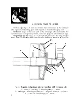
Eyepiece set

 (fig.3) consists of focussing mechanism, diagonal mirror, set of

symmetrical eyepieces f'=25mm and f'=10mm fixed in the mounting of 31.8mm

(1.25”), Barlow lens mounted in the same one.

Finderscope 6

 (fig.1) is a telescope with 8x magnification and view field 7°.

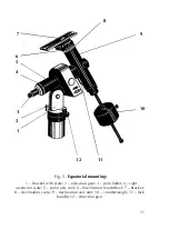
The equatorial mounting

 (fig.5) comprises the polar axis unit 5 and

declination axis unit 9 that are perpendicular each other. The declination axis

unit is provided with the bracket 7 for telescope tube on the one side and with

the movable counterweight 10 on the other side to adjust the telescope balance.

The pole finder 3 inside the polar axis unit is provided to align the mounting

with the polar axis. The polar axis unit is attached to the bracket 1 provided

with the latitude scale. The alignment to polar axis is ensured by means of

elevation gear 2 and direction gear 12.

The mounting is provided with the watch drive inside for automatic tracking

a celestial object at specified speed.

Each of axis units is provided with the setting circle 4, 8 to define the right

ascension and declination angles of an object viewed.

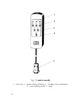
The buttons 2 of the control console (fig.7) select three tracking rate: they

are the celestial, solar and lunar speeds; and the buttons 3 can switch on two

adjustment mode which speed up or slow down the tracking with factor 2.

The control console is connected to the mounting by means of plug 5. The

control console is provided with the local lighting activated by the button 4.

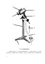
Pier 3

 (Fig. 1) consists of a pipe with three supports 4.

The tripod

 (Fig. 2) allows to adjust a height of telescope and to fix each leg

of tripod with the help of stops 1 and 2. It is completed with table 3.

Supply unit 7

 (a step-down transformer) is designed for converting of voltage

supply mains 220V, 50 Hz (or 110V, 60Hz) in to the voltage supply 12V which

is necessary to supply a safe operation of telescope.

Summary of Contents for TAL-150K

Page 1: ...1 TELESCOPE TAË 150K Service manual ...

Page 2: ...er of operation 18 7 1 Operation with telescope 18 7 2 Photographic observations 19 7 3 Telescope and atmospheric conditions 19 8 Maintenance 20 9 Rules of storage 22 10 Acceptance certificate 22 Supplement Table of close stellar pairs for testing image quality of the telescope 23 The telescope is subject to continuous development and improvement consequently it may incorporate minor changes in de...

Page 3: ...quality of image Also if it is necessary to leave a telescope out of door for example to dry it one should orient it so that the direct sunlight do not get into the optical system The telescope can operate normally at the ambient temperature from 30 C to minus 30 C It is a precise powerful amateur astronomer telescope It demands a careful handling and certain knowledge in the field of astronomy On...

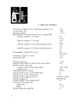
Page 4: ...ngle field of view 40 23 3mm Screening of pupil in center 13 Resolution limit 0 8 Pellucid capacity 13 4m Range of slow motion control on the axes within 4 Rotation of the telescope in right ascension hour long angle 360 24h in declination 360 Operation limit by latitude 0 70 Angular field of view of the finderscope 8 Magnification of the finderscope 6x Voltage of the supplying mains V 220 110V 10...

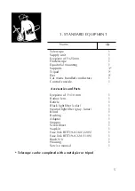
Page 5: ...ctors 1 Control console 1 Accessories and Parts Eyepiece of f 10 mm 1 Barlow lens 1 Reticle 1 Black light filter solar 1 Neutral light filter gray lunar 1 Blind 1 Bushing 1 Adapter 1 Stopper 1 Screwdriver 1 Napkin 1 Fuse link ÂÏT19 0 16À 220V 1 Fuse link ÂÏT19 0 32A 110V 1 Brush N 6 1 Housing 1 Service manual 1 Telescope can be completed with a metal pier or tripod ...

Page 6: ...6 Fig 1 General view 1 telescope tube 2 equatorial mounting 3 control console 4 cable assembly 5 supply unit 6 support 7 pier 8 eyepiece unit 9 finderscope 4 3 2 1 8 9 7 6 5 ...

Page 7: ...7 Fig 2 General view with tripod 1 3 stoppers 2 table 3 1 2 ...

Page 8: ...ical units such as a primary mirror corrector eyepiece set and finderscope The primary mirror 1 fig 3 is fastened with the collet bushing 2 in the center hole The blending tube 3 on the collet bushing prevents stray light The Fig 3 Assemble of primary mirror together with eyepiece set 1 mirror 2 bushing 3 blending tube 4 screws 5 bushing 6 focusing mechanism 7 diagonal mirror 8 eyepiece 9 screw 10...

Page 9: ...ector fig 4 consists of secondary mirror 2 and meniscus lens 3 spaced by means of padding rings 4 in the mounting 1 The corrector is 6 7 2 1 3 4 5 Fig 4 Corrector 1 mounting 2 reflecting lens 3 meniscus 4 padding ring 5 hinge bushing 6 hinge ped 7 adjusting bolt screw 8 cap 8 ...

Page 10: ...lar axis is ensured by means of elevation gear 2 and direction gear 12 The mounting is provided with the watch drive inside for automatic tracking a celestial object at specified speed Each of axis units is provided with the setting circle 4 8 to define the right ascension and declination angles of an object viewed The buttons 2 of the control console fig 7 select three tracking rate they are the ...

Page 11: ...t with scale 2 elevation gear 3 pole finder 4 right ascension scale 5 polar axis unit 6 fine motion handwheel 7 bracket 8 declination scale 9 declination axis unit 10 counterweigh 11 lock handle 12 direction gear 8 9 10 11 1 2 3 4 5 6 7 12 ...

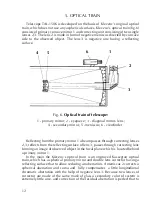
Page 12: ... forming an image of observed object in the focal plane which is located behind a primary mirror 1 In the main the Klevzov s optical train is an improved Kassegran optical train which has a spherical primary mirror and double lens corrector having a reflecting surface that to allow reducing an aberration A meniscus 2 corrects a spherical aberration and coma and fully compensates a little longitudi...

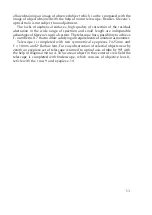
Page 13: ...levzov s optical system The telescope has a possibility to achieve F number to 8 7 that to allow satisfying all requirements of amateur astronomer Telescope is completed with two symmetrical eyepieces f 25mm and f 10 mm and 2x Barlow lens For easy observation of celestial objects near by zenith an eyepiece set of telescope is turned to optical axis of tube by 90 with the help of diagonal mirror 4 ...

Page 14: ...14 1 2 3 4 5 Fig 7 Control console 1 indicator 2 speed selection buttons 3 tracking correction buttons 4 local lighting switch 5 plug ...

Page 15: ... obtaining the required magnification of the telescope the respective eyepiece or the eyepiece with Barlow lens Fig 6 is inserted in the eyepiece tube Set the power switch to position I Connect the power source output 12 V to the socket in mounting Connect the power source to mains 220 V 50 Hz 110 V 60 Hz The power indicator will light Connect the control console to the mounting and press one of t...

Page 16: ...nit must be in compliance with the rate denoted under the fuse link holder Mount the fuse link only after complete disconnection of the supply unit from the mains Connect the bundled conductors to the watch drive and supply unit when the supply unit is disconnected from the mains ...

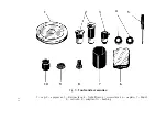
Page 17: ...17 Fig 8 Tools and accessories 1 cap 2 eyepieces 3 Barlow lens 4 light filters 5 screwdriver 6 napkin 7 blind 8 reticule 9 adapter 10 bushing 5 4 3 2 1 6 7 8 9 10 ...

Page 18: ... travel from the Earth s Southern Hemisphere to the Southern one and vice versa you should change the direction of watch drive revolution This procedure is performed once by means of the dedicated switch inside the control console To do it open the control console and set the switch to appropriate position The magnification of the telescope is large and consequently its field of view is low Theref...

Page 19: ...or corrections for a clockwork drive keeping the star on the cross hairs for the whole period of exposure One corrects the position of the guide star with the micrometer screw of the declination axis if necessary To obtain the minimum corrections in declination the polar axis should be set as precisely as possible to the celestial pole One should remember that if the polar axis is set incorrectly ...

Page 20: ... surfaces can get misted under direct sunlight So one should protect the telescope from the direct sunlight It is recommended to stay it in dark cold room for some time But if the mirror got misted it is not necessary to wipe it One should open the telescope and stay it within 30 minutes in daylight The moisture is evaporated in full After operation one should pack the telescope and store it accor...

Page 21: ... surface is cleaned with removed main mirror assembly A cleaning of optical parts and adjusting of telescope is prohibited before warranty expiration It requires care and thoroughness and should be fulfilled in the case of absolute necessity only In the case new adjustment of the telescope is need after a disadjustment or cleaning of optics with reassembling remove the cap 8 fig 4 and view the sel...

Page 22: ...5 C to 40 C It is recommended to avoid any strokes and shakes It is forbidden to store any acid alkali and materials educing moisture or chemical active gas and streams 10 ACCEPTANCE CERTIFICATE Telescope ÒÀË 150K serial is found fit for service Date of manufacture and slushing _________________________________ Signatures __________________________________ ...

Page 23: ...8 Lynx xUma 11h 15 6m 31 49 4 4 4 8 2 9 Ursa Major xBoo 14h 38 8m 13 56 4 6 4 6 1 2 Bootes eBoo 14h 42 8m 27 17 2 7 5 1 3 0 Bootes mDra 17h 04 3m 54 32 5 8 5 8 2 2 Draco tOph 18h 00 4m 08 11 5 4 6 0 2 0 Ophiucus 70 Oph 18h 02 9m 02 31 4 0 6 0 2 4 Ophiucus e1 Lyr 18h 42 7m 39 37 5 1 6 2 2 7 Lyra e2 Lyr 18h 42 7m 39 37 5 1 5 4 2 2 Lyra dCyg 19h 43 4m 45 00 3 0 6 5 2 2 Cygnus mCyg 21h 41 9m 28 30 4 7...

Reviews: