25
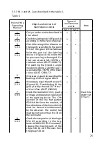
5.3.3 M.- and M.-2 are described in the table 6.
Table 6
Point of the
Operating
Manual
Object and contents of
maintenance works
Types of
maintenance
works
Note
M.-
M.-2
Carry out the works described in
the table 5
+
+
Check the aiming circle 4 (Figure A.4)
according 3.3 to the Service Manual
+
-
Check the recognition distance on
the locality according to the point
5.3.4 of the given Service Manual
+
+
Paint the parts of the sighting
device 4 (Figure A.0) where the
lacquer coating is damaged. For
that use enamel МL-65PМ of
the black colour (GOST 2034-77).
For painting the tripod 3, angle
measuring device 2 and the case
use enamel МL-65PМ of the khaki
colour (GOST 2034-77)
+
+
If necessary, repair the case. Glue the
bushings with nitro glue АK-20
+
-
If necessary, repair the soft covers 5
(Figure A.9), 7 and the bag 8. Use
glossy factory threads 20 "Prima"
of the Class (GOST 6309-93)
+
-
Check the resolution limit, quality
of image and operation resolution
of the sighting device. The 7th
element of the line test pattern
GOI SH-K No 6 must be resolved, all
four directions of the lines of which
must be viewed simultaneously
by the observer. The control test
must be not lower than No 34 on
the collimator
-
+
the Article
UKNP-М
(Yu7-)
Check the integration of the single
STA kit according to the log-
book AL3.803.05 FО. If necessary,
replace the missing parts of the
single STA kit with the ones from
the group STA kit
-
+
5.3.3
3
5.3.3
2
5.3.3
4
5.3.3
5
5.3.3
6
5.3.3
7
5.3.3
8
5.3.3
Summary of Contents for 1PN91-2
Page 1: ...ARTICLE 1PN91 2 Service manual AL3 803 105 RE...
Page 2: ......
Page 37: ...37 2 1 3 1 cap 2 ring 3 cap Figure A 5 The illuminator...
Page 38: ...38 Figure A 6 The field of view of the sighting device...
Page 39: ...39 Figure A 7 The Landolt ring for checking illumination...
Page 40: ...40 Figure A 8 The chart for illumination defining Illumination lux distance m...
Page 43: ...43 1 91 2...


