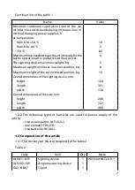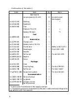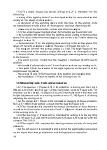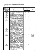
4
3..3 It is recommended to take the tripod 5 (Figure A.2) from the soft cover 7
(Figure A.9) and put the tripod and the soft cover into the case separately. This
is done for reducing the time of setting the article in action position.
3.2 Setting of the article in action position
3.2. For setting the article in action position at night it is necessary to do
the following:
– take the tripod 3 out of the case (Figure A.0);
– take the soft cover 7 (Figure A.9) off the tripod 3;
– set the tripod on the ground;
– take the angle measuring device 2 from the case (Figure A.0), set it into the ball
bearing of the tripod (Figure A.4), having slightly turned the thumbscrew 20 tight;
– level the angle measuring device in the ball bearing of the tripod till the
bubble of the round level 6 is placed in the center of the level vial. Finally,
screw the thumbscrew 20 tight;
– take the sighting device 4 (Figure A.0) from the case and mount it on
the seat 0 (Figure A.4) of the angle measuring device. Turn the handle 9 up
to the stop;
– screw the cap (Figure A.3) out of the sighting device, the lid 3 (Figure A.5) out
of the illuminator. Take four accumulators NLTs-0.9- 4 (Figure A.9) from the
case and set two accumulators in the cap (Figure A.3) and two accumulators
in the cap 3 (Figure A.5). Screw the lids into the sighting device and into the
illuminator;
– if it is necessary to carry out mutual orientation of two observers, take the
handle 3 (Figure A.9) and the screw 9 from the case. Fasten the handle with the
help of the screw through the hole A (Figure A.3) on the sighting device body.
Fix the illuminator 6 (Figure A.9) into the handle hole;
– switch on the sighting device by turning the handle 2 (Figure A.3) to the
position marked with the white point;
– set the diopter value necessary for the eye on the ocular scale by turning
the ring 5 of the ocular;
– take the diaphragm 4 (Figure A.9) off the sighting device objective;
– make the image of the object, which is observed, by turning the
handwheel 2 (Figure A.3);
– release the aiming circle by turning the handwheel 7 (Figure A.4).
3.2.2 Setting the article in action position in the daytime and at dusk must
be carried out in the same way as at night. The only difference is that the
diaphragm 4 (Figure A.9) is not taken off the sighting device objective.
3.3 Checking and adjusting of the aiming circle
3.3. Checking of the aiming circle includes checking coordination of the
aiming circle needle with the observing line of the device (checking aiming
circle according to the direction); checking deviation of the upper surface of
Summary of Contents for 1PN91-2
Page 1: ...ARTICLE 1PN91 2 Service manual AL3 803 105 RE...
Page 2: ......
Page 37: ...37 2 1 3 1 cap 2 ring 3 cap Figure A 5 The illuminator...
Page 38: ...38 Figure A 6 The field of view of the sighting device...
Page 39: ...39 Figure A 7 The Landolt ring for checking illumination...
Page 40: ...40 Figure A 8 The chart for illumination defining Illumination lux distance m...
Page 43: ...43 1 91 2...


