Timer NT240
NOVUS AUTOMATION
2/5
Connections of the input signals
The type of signal to be applied to the inputs is determined by the
user in the
PnP
parameter of the timer. The signal type must be the
same for the three inputs (Start, Hold and Reset).
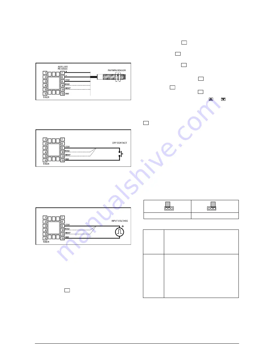
Sensors with NPN/PNP open collector output:
Common to most proximity sensors, must be connected as indicated
in Figure 02. The
PnP
parameter must be set to 0 for NPN sensor
output and to 1 for PNP.
Figure 02 – Connecting PNP/NPN type sensor
- Signal from relay or switch (dry contact):
Wire dry contacts as shown on Figure 03. For this type of input,
configure
PNP
= 0.
Figura 03 - Conectando contato seco (relé, interruptor)
- Voltage input signal
Refer to the “Specifications” section for the input voltage levels
compatible with the timer. Figure 04 shows the wiring scheme.
When
PNP
= 1, the timer recognizes the rising edge of the pulse
For the recognition of the falling edge, set
PnP
= 0.
Figure 04 - Connection for pulse input.
OPERATION
Following power-on, the timer shows the main screen (Time) and will
remain in this screen in normal operation.
For configuring the timer, it is necessary to set proper values to the
various internal parameters.
The parameters are organized in three levels. To enter these levels,
one must press the
P
key for defined intervals of time, as shown
below.
Levels structure:
1 Indication of elapsed time
Shown on power-up;
2 Setpoint level (temporization setpoints)
To enter, press
P
for 4 seconds;
3 Configuration level.
Press
P
for 8 seconds;
4 Custom Operating mode level.
Press
P
for 12 seconds;
To enter into deeper levels, press the
P
for the time required by
the level and when the timer shows the first parameter of that level,
simply release the
P
key to stay in that level. Other parameters in
that level are accessed by pressing the
P
key.
To modify the value of a parameter use the and keys for
incrementing or decrementing the value, respectively. After the last
parameter of the cycle is reached, the timer returns the main screen
(Indication of Elapsed time).
The modified values are stored in a non-volatile memory when the
P
key is pressed to move to the next parameter.
PROGRAM SECURITY
To avoid tampering, parameter “
Prot
” and a hardware jumper can
be used to disable access to programming parameters.
With the jumper in the OFF position, all program levels are
unprotected. The “
Prot
” parameter can only be changed with the
jumper in the OFF position.
With the jumper in the ON position or removed, the protection level
is defined by the current value of the “
Prot
” parameter:
0
No protection. All parameters can be accessed;
1
No access to Operating mode level.
2
No access to Operating mode level and Configuration level.
3
Full protection.
OFF
ON
Figure 2 – Protection Disabled
Figure 3 – Protection Enabled
Temporization Setpoints Level
T1.sp
Timer 1 SetPoint
Timer Setpoint: It defines the total time to be
counted by the timer. In up counting, the timer
counts from zero to the value programmed in
t1.SP
. In countdown, the timer counts from the
value programmed in
t1.SP
to zero.
0v1.t
Output 1 Time
Output temporization: Defines the interval of time
the output is to remain active after the time
programmed in
t1.SP
has elapsed (parameter
T1.S4
shall be set to 1
output turns off after
output temporization).
During the output temporization the relays are
maintained active while the corresponding LEDs
blink to indicate the output temporization is taking
place.


