N1040 Controller
NOVUS AUTOMATION
2/7
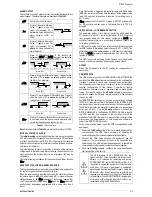
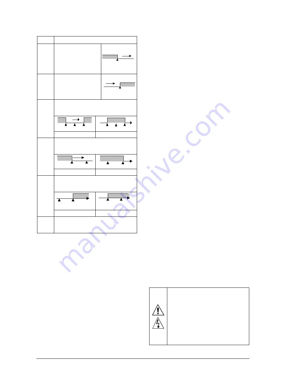
ALARM OUTPUT
The controller contains 2 alarms that can be directed (assigned) to any
output channel. The alarm functions are described in Table 02.
off
Output is not used as alarm.
lo
Alarm of Absolute Minimum
Value. Triggers when the
value of measured PV is
below the value defined for
alarm
Setpoint
.
(SPA1 or
SPA2)
.
SPA1
PV
ki
Alarm of Absolute Maximum
Value. Triggers when the
value of measured PV is
above the value defined for
alarm
Setpoint
.
SPA1
PV
dif
Alarm of Differential Value. In this function the
parameters
SPA1
and
SPA2
represent the deviation
of PV in relation to the SP of CONTROL.
SP
PV
SP + SPA1
SP – SPA1
SP
PV
SV – SPA1
SV + SPA1
Positive SPA1
Negative SPA1
difl
Alarm of Minimum Differential Value. It triggers when
the value of PV is below the defined point by (using
the Alarm 1 as example).
SP
PV
SP – SPA1
SP
PV
SP – SPA1
Positive SPA1
Negative SPA1
difk
Alarm of Valor Maximum Differential Value. Triggers
when the value of PV is above the defined point by
(using Alarm 1 as example):
SP
PV
SP + SPA1
SP
PV
SP + SPA1
Positive SPA1
Negative SPA1
ierr
Alarms of the Sensor Break (Sensor
Break Alarm
). It
is activated when the Input presents problems such
as interrupted sensor, bad connection, etc.
Table 02 – Alarm functions
Note: Alarm functions on Table 02 are also valid for Alarm 2 (SPA2).
INITIAL BLOCKING OF ALARM
The initial blocking option inhibits the alarm from being recognized
if an alarm condition is present when the controller is first energized
(or after a transition from run YES
NO). The alarm will be enabled
only after the occurrence of a non-alarm condition followed by a new
occurrence for the alarm.
The initial blocking is useful, for instance, when one of the alarms is
configured as a minimum value alarm, causing the activation of the
alarm soon upon the process start-up, an occurrence that may be
undesirable.
The initial blocking is disabled for the sensor break alarm function
ierr
.
SAFE OUTPUT VALUE WITH SENSOR FAILURE
This function defines an output value (user defined) to be assigned to
the control output in the event of a sensor failure.
When the input sensor is identified as broken, the controller switches
the control mode to MANUAL while forcing MV to assume the user
configured value in the
1E.ov
parameter. This function requires that
one of the alarms be configured as
1Err
and the
1E.ov
parameter
(control output percentage) programmed with a value other then 0
(zero).
Once this function is triggered, the controller remains in SAFE mode
(MANUAL control output) even after the sensor failure appears to be
fixed. The operator intervention is required for switching back to
AUTO mode.
1E.ov
values are only 0 and 100 % when in ON/OFF control mode.
For PID control mode any value in the range from 0 to 100 % is
accepted.
LBD FUNCTION – LOOP BREAK DETECTION
The parameter defines a time interval, in minutes, within which the
PV is expect to react to a control output signal. If the PV does not
react properly within the time interval configured in
lbd.t
, the
controller interprets this as a control loop break and signals this
occurrence in the display.
A LBD event may be sent to any output channel. Simply configure
the LDB function to the desired output channel (OUT1 or OUT2): the
selected output will be activated when a LDB condition is detected.
When the
Lbd.t
parameter is programmed with 0 (zero), the LDB
function is disabled.
The LBD is useful in detecting system failures, such us defective
sensors or actuators, loads and power supply, among others.
OFFSET
Allows fine adjustments to the PV reading for compensation of
sensor error.
USB INTERFACE
The USB interface is used for CONFIGURING or MONITORING the
controller. The
NConfig
software must be used for the configuration.
It makes it possible to create, view, save and open configurations
from the equipment or files in your computer. The tool for saving and
opening configurations in files makes it possible to transfer
configurations between pieces of equipment and to make backup
copies. For specific models, the
NConfig
software also makes it
possible to update the firmware (internal software) of the controller
through the USB.
For MONITORING purposes you can use any supervisory software
(SCADA) or laboratory software that supports the MODBUS RTU
communication on a serial communications port. When connected to
the USB of a computer, the controller is recognized as a conventional
serial port (COM x). Use the
NConfig
software or consult the
DEVICE MANAGER in the Windows CONTROL PANEL to identify
the COM port that was assigned to the controller. Consult the
mapping of the MODBUS memory in the controller’s communications
manual and the documentation of your supervisory software to
conduct the MONITORING process.
Follow the procedure below to use the USB communication of the
equipment:
1.
Download the
NConfig
software from our website and install it on
your computer. The USB drivers necessary for operating the
communication will be installed together with the software.
2.
Connect the USB cable between the equipment and the
computer. The controller does not have to be connected to a
power supply. The USB will provide enough power to operate the
communication (other equipment functions cannot operate).
3.
Open the
NConfig
software, configure the communication and
start recognition of the device.
The USB interface IS NOT SEPARATE from the
signal input (PV) or the controller’s digital inputs and
outputs. It is intended for temporary use during
CONFIGURATION and MONITORING periods. For
the safety of people and equipment, it must only be
used when the piece of equipment is completely
disconnected from the input/output signals. Using the
USB in any other type of connection is possible but
requires a careful analysis by the person responsible
for installing it. When MONITORING for long periods
of time and with connected inputs and outputs, we
recommend using the RS485 interface.

